dingy
-
Posts
5,403 -
Joined
-
Last visited
Content Type
Profiles
Forums
Gallery
Events
Store
Everything posted by dingy
-

Hunt for a Boost Sensor
dingy replied to MasterGuns's topic in Venture and Venture Royale Tech Talk ('83 - '93)
It is actually apressure sensor in that it varies the output voltage dependant on the difference between normal air pressure and what the intake manifold/carb venturi pressure is, which is lower than normal, so it would be refered to as a vacuum. I think parts fiche calls it a boost sensor and it may even be molded into sensor housing. Gary -
If you are in that deep, it would be a good time to fix the starter ground. http://www.venturerider.org/forum/showthread.php?t=46890 Gary
-
Help-valve shim tool
dingy replied to dug050's topic in Royal Star and Royal Star Tour Deluxe Tech Talk
In the 2nd picture it looks like the side ramp cuts are deeper than the stock one. Is this just photo perception problem? If the back center protrusion is narrower, it would allow the tool to possibly shift one way or the other and slip off cam bucket on one side. Its probably just the photo though. Gary -
You can use a TCI from 84-89 on the 83. It will require the vacuum tube that goes to the #2 carb (LF) to be moved to the intake manifold port & the existing port on the carb body plugged. Gary
-
Need a 1st Gen MKII front rotor
dingy replied to dingy's topic in Venture and Venture Royale Tech Talk ('83 - '93)
Thanks Bob. I know my MKII rotors are marked R & L, but I didn't see a reason I couldn't reverse it. I would want the slots in the rotor face to be trailing. Or would that matter? 1st picture. 2nd picture shows clearance with Vmax wheel in place rotor is clear, but not enough for a Venture caliper arm. I need to use VMax style in 3rd pic. It uses a torque arm from the top of the caliper arm to the swing arm to retain caliper arm rotation. Gary -
I need a usable, front rotor off an MKII. Right or left per Bongo. I am putting it on rear wheel as part of my VMax wheel conversion. I have to use the VMax rear brake and mounting setup due to swing arm clearance issues. The VMax uses a 282 rear rotor, which is the same diameter as a 1st gen front. 1st gen is 1mm thicker, but it will work for what I am doing. MKII rear brake setup I have on now with the 320mm rotor isn't even close to being able to make to work due to the offset in the floating rotor design. I could make my 298mm MKI rear rotor work, but it wouldn't be an exact match either. Gary
-
If you go fast enough, maybe the small dirt particles in the air would be like a bead blaster !!!! Gary
-
86 VR 2nd Gear Indicator problem
dingy replied to Zfrebird4's topic in Venture and Venture Royale Tech Talk ('83 - '93)
All of these are grounded connections, switch puts a ground signal to CMU. If you are going to replace the pin, replace the spring. One I just rebuilt that was in picture, the old spring was noticeably shorter than the new one. You might get by, in a half ass manner but, drivable, if you were to clean everything and stretch the spring a little bit so as to put more pressure on pin. Prices below are from partshark.com, I don't know what options you have in Canada. Spring is P/N 90501-06022-00 $1.82 US Pin is P/N 4UN-18542-00-00 $2.16 US Switch O-ring P/N 93210-29196-00 $2.38 Switch is probably reusable, if it is not grooved much. Fix wires as needed. Gary -
86 VR 2nd Gear Indicator problem
dingy replied to Zfrebird4's topic in Venture and Venture Royale Tech Talk ('83 - '93)
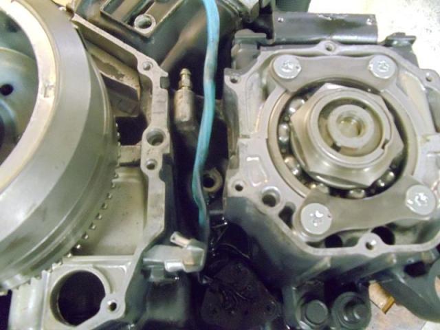
Does neutral light go out when motor warms up? The loctite was in reference to the pin in the end of the shift cam. (See last picture in this post) Do not use loctite where the screw will be threaded into a plastic part. In the case of this switch, loctite probably isn't needed. First, you need clean dry screw holes for loctite to work. I really don't think pulling the stator cover is going to help a lot. I just looked at mine and it will very little. Attached are a few more pictures I just took. 1st one, switch is just visible over blue cable/side stand switch boot. It is painted black in these pictures. You can see the difference in the stator cover to the left of picture. It is a glossy, powder coated black, the block is a flat black. Your not going to gain much by removing stator. 2nd picture shows view up from bottom. The exhaust is not on in this picture, so you won't have this access to it. It just shows orientation. 3rd picture shows a straight in view. It isn't real easy to get it in there, but it is doable. When you put screws in, you can use a piece of tape to hold them to the phillips tip to get them started. The switch plate will snap into place, it may need some rotational tweaking. Last picture shows the shift cam unit out of the block. All you will see is the very top surface with the brass 'button' sticking out. This picture shows a brand new button in place. Yours will be worn down some almost for sure. If it real bad compared to this, it should be replaced also. This is the screw I mentioned earlier that needed heat to loosen, and should be loctited back in. It is a torx head screw. Gary -
86 VR 2nd Gear Indicator problem
dingy replied to Zfrebird4's topic in Venture and Venture Royale Tech Talk ('83 - '93)
I added 2 more thumbnail pictures to my first post to try to give a little better depth feeling. The one with the case split, the pocket is straight in from where the bottle of loctite is setting. All these pictures are with a normal style click & shoot digital camera. Once you get the three screws out, the switch will pop out very easily. There is about a 1/4" lip that engages with the block. It can only go back in one way and get all three screws to engage. The shift cam pin will not come apart at this point. There is a screw in the end holding it together. I had to heat this screw up to get it loose, think it had red loctite on it. Previous pictures were not clean. The very last one I added of the block split is clean. Gary
-
Inexpensive whine/chirp fix
dingy replied to remmertb's topic in Royal Star Venture Tech Talk ('99 - '13)
I will have to say, I don't recall 1st genners complaining about the whine. At least from the clutch. Gary -
Hunt for a Boost Sensor
dingy replied to MasterGuns's topic in Venture and Venture Royale Tech Talk ('83 - '93)
Gunney, Sending you two of them, one of an 83 and one from an 88. I tried bench checking the 83, but I didn't get reading I expected. Didn't try to check the 88 so as to not mess it up. Should be there by Tuesday. Tracking # 9101785091401089768147 Gary -
I agree with Squidly on using a stock R/R. As long as it is in good condition and has high quality connections. Something else that would be very helpful that has been mentioned before on this forum is to run a heavy gauge wire from the regulator to the battery. Do this on the red (positive) & black (negative) wire. Use at least 12 gauge wire. If you have the type of regulator that has a brown wire, it's OK as is. This was used a voltage sensor. Reason this helps is that inside of the wiring harness there are a couple of crimp style connections between the regulator & the battery that can become high resistance with all the vibration & other various factors that they are subject to. Especially the ground wire side. It has connections all over. There is one connection in particular on the VMax's that is notorious for causing problems. Venture harnesses are of course different, so problem could be similar at other points. If you are going to run the extra wires, I would SOLDER them into the R/R right next to the body of the R/R. In other words, don't go through the R/R connector, less chance for a high resistance problem. Solder a ring type connection on the battery end and screw it right to the posts. It would be prudent to put at least a 30 amp fuse in line with the positive wire as close to battery as can be. I know the 1st gens have a 40 amp main fuse, but this wire will not carry the full load, it is in parallel with existing wiring. 40 amp fuse holders are not commonly available. Gary http://i1007.photobucket.com/albums/af193/gdingy101/wiringdaigramforrectifier.jpg
-
Hunt for a Boost Sensor
dingy replied to MasterGuns's topic in Venture and Venture Royale Tech Talk ('83 - '93)
Send me a PM, I have a good one I will part with. Don't use it any more. Gary -
Attached below is a picture of a typical charging system in a Venture, this happens to be from an MKII. Newer models don't have the brown wire going to the regulator/rectifier anymore. As you can see, both ends of each of the six main diodes are available on a given pair of wires. Left side all tie to the red wire on the cathode (-) side and on the right side all three tie to the ground wire on the Anode (+) side. Below is a somewhat confusing way to check the six rectifying diodes and see if the are open or shorted. This does not address checking the zener diode (one with the squiggly line in lower left.) If any of these diodes do not read as they should, R/R is junk. Even if these all check out OK though, there is other parts of the R/R that can't be checked. So this procedure will only tell you for sure if R/R is bad, it can't verify completely that it is good. In essence, you will be reading current flow through each diode in one direction, then reversing current flow. Current flow is permitted in the direction of the arrow in the diode schematic, but blocked when flowing against arrow. When you put the red lead of the back side of the arrow and the black lead on the point side of the arrow, it should read zero (or near) ohms, reverse the leads and it should read high ohms. By taking an ohm meter and placing the Red (+) lead of the meter on the red wire of the regulator and then probing each of the three white wires with the black lead of the meter, this reading should be near infinite ohms (open/high ohms) on each wire. Now put the Black (-) lead of the meter on the red wire of the regulator and then probing each of the three white wires, this reading should be near zero ohms on each wire. Repeat procedure on other bank of diodes as follows, the Black (-) lead of the meter on the black wire of the regulator and then probing each of the three white wires with the black lead of the meter, this reading should be near infinite ohms (open/high ohms) on each wire. Now put the Red (+) lead of the meter on the black wire of the regulator and then probing each of the three white wires, this reading should be zero ohms on each wire. Also attached the page from service manual, its probably easier to understand. Gary
-
Below is a not brief summary of the reserve lighting unit operation. This is what I have found with the operation of a working system on an 1988 wiring setup. I have just verified this information on my bike. I have independent spade lug terminals hooking up to the headlight plug in the wiring harness,due to my projector headlights, so it is easy to simulate burnt out bulb conditions. The reserve lighting unit is located on the right side of the headlight unit. When the dimmer switch is set to LOW and low beam lamp is not functioning, the reserve unit illuminates the high beam lamp at a reduced voltage, this keeps from blinding oncoming traffic. The dash white indicator light "Headlamp" is illuminated. CMU Headlight icon is displayed. When the dimmer switch is set to LOW and High beam lamp is not functioning. The dash white indicator light "Headlamp" is not illuminated. CMU Headlight icon is displayed. When the dimmer switch is set to HIGH and High beam lamp is not functioning, the reserve unit illuminates the low beam lamp at a near normal voltage. The dash white indicator light "Headlamp" is illuminated. CMU Headlight icon is displayed. The "High beam" indicator is lit. When the dimmer switch is set to HIGH and Low beam lamp is not functioning. The dash white indicator light "Headlamp" is not illuminated. CMU Headlight icon is displayed. The "High beam" indicator is lit. When both lights are not functioning, only the CMU icon is displayed when Low beam is selected. When HIGH beam is selected, the dash white indicator light "Headlamp" is illuminated. CMU Headlight icon is displayed. And the "High beam" indicator is lit. Assuming the wiring diagrams are correct, the high and low beam run through the CMU. There is an input circuit and an output circuit for both the high and low beams. The reserve lighting unit is where the input wire from the headlight fuse goes first. I am guessing that the current on this wire is used to determine if the lamps are lit or not. Last paragraphs are based on this assumption. If the Low beam is selected at the dimmer switch, a positive voltage is sent to the CMU, which then passes that voltage back to the headlamp. If headlamp is burning, reserve lighting unit does nothing. It senses normal current on feed wire, and it is getting voltage on its low side input. If the High beam is selected at the dimmer switch, a positive voltage is sent to the CMU, which then passes that voltage back to the headlamp. If headlamp is NOT burning, reserve lighting unit senses very low current on feed wire (some current consumed in CMU), and it is getting voltage on its low side input. The reserve lighting unit then outputs reduced positive voltage on the High beam circuit, thus illuminating High beam and signaling CMU that low beam filimant is burnt out. If the High beam is selected at the dimmer switch, a positive voltage is sent to the CMU, which then passes that voltage back to the headlamp. If headlamp is lit, reserve lighting unit lights the High beam indicator lamp. It senses normal current on feed wire, and it is getting voltage on its high side input. If it is not lit, the reserve lighting unit outputs positive voltage on the low beam circuit, thus illuminating low beam and signaling CMU that high beam filament is burnt out. Gary
-
I don't see a problem taking them apart this way. Where I get concerned is when you put them back together, how do you set torque on the bottom bolt? Gary
-
Brake rebuild question
dingy replied to mitch77's topic in Venture and Venture Royale Tech Talk ('83 - '93)
I can not see why delinking the brakes would change the amount of time it takes to rebuild the calipers. There are still 3 calipers, 2 master cylinders any way you look at it. Only time difference in my opinion is that it is easier to bleed delinked brakes. But that small time savings would be small compared to the time it takes to do the delink surgery, not to mention the needed parts to complete this. Brake line from front master to a new splitter, then new lines from splitter to both front calipers. Roughly $100 in parts for 3 new stainless steel lines and a used Vmax splitter. I suggest you find a competent mechanic. Gary -
Roll one, Smoke one. Repeat
-
This is what a stock set of 1st gen mufflers sound like with all but the 1st baffle removed. 1300 motor. Ignore the video, I don't know how to strip out the sound only. [ame=http://www.youtube.com/watch?v=u3K3CKEMxvA&feature=player_embedded]YouTube - Map w can [/ame] Gary
-
One of the moderators just needs to mark this thread closed for posting. After above comment, it's NUFF SAID !! Gary
-
This is the Harbor Freight unit I used last year. Has a much better looking front chock than what is in the catalog now. Gary
-
Save folders for PMs
dingy replied to Snaggletooth's topic in Computer help and tips for using this site.
At lower right side of Private Message screen, There is a Move to Folder option (Selected Messages) in a pull down menu. When you open this pull down, you can save your messages in 3 different formats. Text, CVS & excel. You can save your messages to your PC, then delete the old ones on the forum, thus freeing up room. You have to do this for each folder you have. Sent & incoming and any others. Gary -
Not sure if Rick is going to follow up. The adjustment takes up the free play, so the lever is fully engaged when it is at its farthest point away from the throttle grip. This allows any movement of the lever to be fully transmitted to the plunger and also sets the actuation of the brake light switch on the RSV (I believe). If there were play at this point, you could have to pull the lever in a 1/2" or more before you started engaging brakes and you might then not have enough lever travel to fully engage brakes. Don't have a good answer as to why clutch don't have same screw. Gary
-
I asked Don and he didn't have an official count. I would guess 250 -300 though. We had at least 140 at the Friday night dinner. Gary