dingy
-
Posts
5,403 -
Joined
-
Last visited
Content Type
Profiles
Forums
Gallery
Events
Store
Everything posted by dingy
-
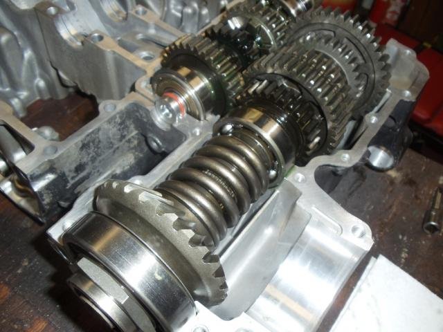
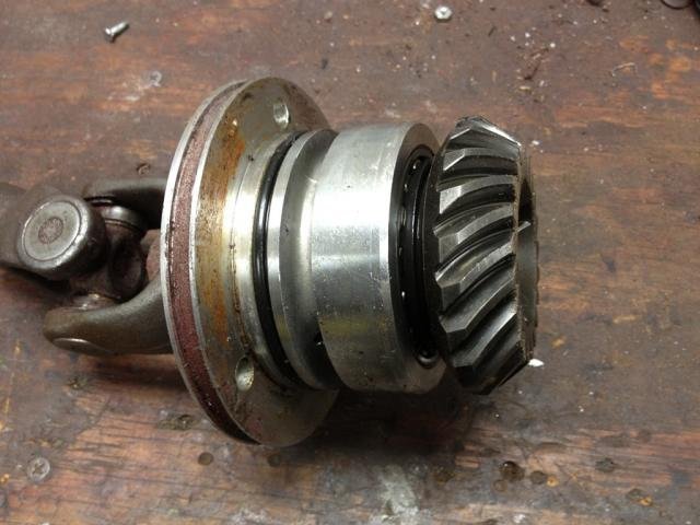
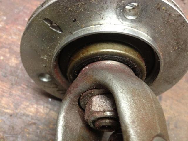
 You have 2 potential leak paths at the middle drive gear. 1st attached picture shows the block without the gear & housing in place. 2nd shows case split with opening at the lower right. Smooth bore into the case. 3rd picture shows the outer housing & o-ring of the middle drive. The outer housing is held stationary by 3 bolts and is sealed by the o-ring. 4th picture shows a rear view of the housing assembly. Just forward of the universal joint is the crush washer that seals the rotating gear shaft to the housing. If you have to pull the middle drive cover out, there will be 1 or more sets of shims between rear of case & housing. These shims will be in 2 pieces per set. If there are more than 1 set of shims in there, they can be different thicknesses, so they must be replaced as a matched pair. You don't want both thick ones on top and both thin ones on the bottom, this would cause gear mating problem. Gary
-
Bike not catching on start
dingy replied to chukzelda's topic in Venture and Venture Royale Tech Talk ('83 - '93)
Listened to your sound clip. First guess is idling to low. Carbs need sync'ed. Idle mixture screws may need adjusted. Carbs may need tore down and cleaned, there are 4 jets in each carb and one is very tiny, happens to be the idle one. Gary -
Bike not catching on start
dingy replied to chukzelda's topic in Venture and Venture Royale Tech Talk ('83 - '93)
Top spot is for the ACCY fuse, 2nd is headlight 10A, 3rd is Ignition 15A, 4th is Signal 15A, 5th is Tail 10A. Wiring diagrams are located at link below. http://www.venturerider.org/forum/showthread.php?t=42358 Gary -
Another new way to mount stuff on a 1st gen handlebar.
dingy replied to Snaggletooth's topic in Watering Hole
Speaking of long drawn out farts Fool, how are the valve shim tools doing?? Haven't heard anything about them for a long time. Gary -
Bike above is a 2007 RSV Craig, what CAD package do you work with ? I saw your occupation in your profile. Also, thread below helps people see what bike you have. http://www.venturerider.org/forum/showthread.php?t=58880 Gary
-
Keep in mind that the wire from the switch is a 12V negative lead. You need to put a 12V positive lead to the relay circuit coil you should install. The attached picture shows the addition of an air horn in addition to the 2 stock horns. New wiring is inside dashed lines. Gary
-
The clear coat was the only place I had any runs as well. It was tougher to tell how much I was putting on. The mixing part is very easy with the cups Sherwin Williams had. There are a series of 'charts' on the mixing cups so that different ratios and different amounts can be accurately combined. I think it was the clear coat that took 3 ingredients. Sherwin also supplied printed instructions for each of primer, color & clear products that detailed the mixing ratios, pot life, recoating times etc. As I mentioned earlier, a decent charcoal resperator is a must have item. Mine was under $20 bucks new off ebay. I also got a cloth hood that covered head to keep paint off some. Lowes had them for under $5. Also attached datasheets for color paint so you can see info you get. For a Sherwin Williams product, you need to go to an automotive paint outlet, they also have house paint stores, but they are two totally different stores. Gary
-
What are these resistors for? 91 VR
dingy replied to GolfVenture's topic in Venture and Venture Royale Tech Talk ('83 - '93)
Explain the term 'blew it out', that would be very unlikely situation in this circuit to damage a resistor. There is likely only milliamps of current flowing. What would be damaged by doing it without the resistor is an IC in the CMU. Some where there is a fix for replacing this IC. Gary -
I carry a plug kit & a CO2 infiltrator kit. The CO@ uses cartridges like a pellet gun uses. have about 6 of the cartridges. Never had to use it, so I don't know how many it would take to inflate a tire. Gary
-
TCI Problems
dingy replied to Dragonslayer's topic in Venture and Venture Royale Tech Talk ('83 - '93)
I doubt it, if it were a case of removing them, then the possibility of this connector would then be a lower probability of being the cause. Other words, if the coils jumpers are redundant, then the TCI would be less likely to fail. I think they may be reading the trailing edge of the lobe as it passes the TCI pickup and using that collapse of the field in the program logic. But until proven it doesn't help it would be an interesting experiment that I can't see causing harm for a short duration test. Gary -
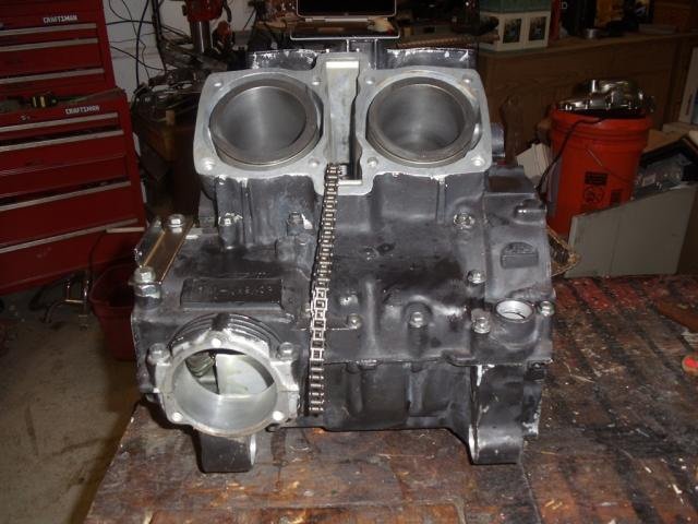
Gary, Below is an idea of what your motor would look like. The block & heads are a satin black high temp engine paint The covers are a high gloss powder coat. This block is from a parts bike I got from MiCarl several years ago. The block was not attractive when I got it. It just takes time to clean it up and paint it. The regular paint Lewis used will be fine. It is time and labor intensive, but these bikes can be brought back to life. Gary
-
TCI Problems
dingy replied to Dragonslayer's topic in Venture and Venture Royale Tech Talk ('83 - '93)
Below is reply I got from Ignitech today about TCI dropping out. About what I expected, if not a little more from them. Pictures are just about going to be impossible, i know. I have put about a 100 miles on mine with out a sign of the problem. One of the points I would think could be a possible suspect is the 6 pin connector that comes from the pickup coils in the Stator housing and connect to the main harness. 6 pin connector with one blank space. I suspect this connection may be the source for many of the stock TCI issues. I helped a member in Columbus OH, last year and this connection was full of grity like sand. After it was cleaned out bike started and ran decent. One of the tidbits about the Ignitech is they manipulate the pickup coils by running only 2 leads into the TCI instead of the stock 4. I had a VMax guy that bought my V80 unit and I knew it ran fine, but we had a heck of a time with it on the VMAx. He finnally pulled the stator cover and one of the pickups was loose and damaged. He replaced the pickups and bike is running as it should. His initial reason for getting the ignitech was a low performing #3 cylinder, which is a very common complaint. Wiring diagram for the pickup coil attached below, both 1 & 4 version. Also a few pictures of connector. It is located near the shock damper adjuster on left side. Gary Gary Hello Colleague has tested units version 80 and 88 he haven’t found any problems and both version work the same way. Could you or your customers make some videos photos etc. Regards Jan Matous Ignitech s.r.o. -
I don't see any pictures since 4/14. I vote we get a moderator to close this thread for lack of viable input from the OP. Gary
-
Anybody Upgraded Their Front Brakes?
dingy replied to bongobobny's topic in Royal Star Venture Tech Talk ('99 - '13)
The axle center line to brake line connection point can be a 'rough' measurement. This is just a check to insure the stock brake line will reach port on caliper. It would be better to get me a vertical, then a horizontal distance. I don't need a 'Z' axis (in/out along axle), this won't make much if any difference. A straight line distance is sort of an ambiguous way to do it, the straight line will help with the other 2, to triangulate and verify point. Within 1/8" is great on this measurement. The critical one is from inside of fork ear to outside face of rotor. Also rotor thickness will be needed, I have to center caliper over C/L of rotor. Another picture that would be nice is a shot looking straight in at rotor, taken with lens at axle C/L, taken about 3 to 4 feet back to cut down on perspective changes. High res is nice. I can place this picture into CAD package and look at fitment of bracket. I can use the to fork holes which are a known distance to scale image. Gary -
HELP! cant get brakes bled!
dingy replied to reddevilmedic's topic in Venture and Venture Royale Tech Talk ('83 - '93)
Just swap the switches out. There is a hole in underside of master that a tab on the switch locks into. Take a small screwdriver and push up tab and switch should slide out. Gary -
HELP! cant get brakes bled!
dingy replied to reddevilmedic's topic in Venture and Venture Royale Tech Talk ('83 - '93)
This will be a dumb idea, but it's about where you are at right now... Did you put cup on backwards ?? It won't build any pressure if you did. Don't even remember if you can. Gary -
I vote for carb sync also. This has a dramatic effect at idle on header temps. This I know. Just fixed this a week ago on mine. Gary
-
Anybody Upgraded Their Front Brakes?
dingy replied to bongobobny's topic in Royal Star Venture Tech Talk ('99 - '13)
Bear with me on some of my questions, I have zero RSV hands on experience. In your 4th picture, it shows the caliper mounted to an adapter bracket that bolts to the fork. This adapter bracket will go away with the Radial bracket. Are the holes in the fork 100mm apart? Probably are but it is important !! Gary -
OK looking at your 2nd picture in this quoted post. What the heck good does a headlight adjust knob do you where that one is located ? Under the fairing, between the forks, that was a cost cutting move if I ever saw one. Heck with that linkage bar we spent big Yen for on those old Maytags, we will improve this baby. The 1st gens have the very same knob located on the dash, you can adjust headlight while riding and with bike loaded to whatever condition. Looks like you could not reach this sitting on the bike. Gary
-
Relay for driving lights
dingy replied to Billkroeger's topic in Venture and Venture Royale Tech Talk ('83 - '93)
This thread may help your understanding of relays. Grab a cold beverage first, it's lengthy. http://www.venturerider.org/forum/showthread.php?t=43150 Gary -
84 VR turn signal switch
dingy replied to a topic in Venture and Venture Royale Tech Talk ('83 - '93)
Per the parts fiche, the 84 choke cable is different. P/N 41R-26331-01-00 The 83 P/N is 26H-26331-00-00, then in 85~93 this number was restated. I have a spare choke cable if needed. Gary -
See post 31 in thread below. There is info & pictures of a 700 deg RTV sealant that will work. http://www.venturerider.org/forum/showthread.php?t=67487 Gary
-
Anybody Upgraded Their Front Brakes?
dingy replied to bongobobny's topic in Royal Star Venture Tech Talk ('99 - '13)
To start I need: From outer face of rotor to inner face of caliper mount surface on fork. Thickness & dia. of rotors. An approx. location of the lower end of the brake line connection point to the caliper, this would work best if done from axle C/L Gary -
Anybody Upgraded Their Front Brakes?
dingy replied to bongobobny's topic in Royal Star Venture Tech Talk ('99 - '13)
I am on that Vmaxforum.net some, but not as much as here. Gary -
HELP! cant get brakes bled!
dingy replied to reddevilmedic's topic in Venture and Venture Royale Tech Talk ('83 - '93)
Yammer Dan was who I learned about the zip tie trick from. He will forever be known for this and his penchant for Sea Foam. Gary