bkuhr
-
Posts
951 -
Joined
-
Last visited
Content Type
Profiles
Forums
Gallery
Events
Store
Everything posted by bkuhr
-
 I think it is unlikely the cmu is defective, or lost either power or ground to it. Most likely,something has happened behind the dash to loosen a plug, or god forbid, you have a critter such as a mouse behind the dash doing a number for you. I guess the first action would be to try to verify if you actually have a fault for each circuit. 1. Test kickstand switch. Engine running, kickstand up, clutch in, place in gear then lower kickstand. Engine should die. This is not foolproof, because the lcd uses a different contact in the kickstand switch from what the engine kill used, but should be good enough if remaining tests also indicate no real problems. 2.The brake light tests for low brake fluid level in both (front and rear) brake master cylinders. Pretty sure the cmu sees a short to ground when both masters a full. When the ground goes away the fault segment should light. Find the wires going to the front master reservior, disconnect both white/blue wires. You will not be able to determine which goes to cmu or the rear master. Apply a ground to the bike side of both white/blue wires for at least 30sec each and see if the lcd goes out. If so the cmu is working any you have a real problem with front or rear or both masters. 3.The engine oil level sensor pretty, sure is opposite the brake level sensors, and indicates a fault when it see's a ground. Find the wire, crusted with dirt, on bottom of motor. Disconnect it and the lcd should go out. Likely the crud was causing a ground, and a good cleaning will solve this. 4.The headlight icon monitors BOTH the High and Low beam headlight. This is an actual current(amperage) monitor system. Try the H-L dimmer and VERIFY it actually changes both elements of the bulb. The reserve lighting system can over-ride a bad filiment and force the other than selected filiment on. If this is happening the white dash RLU light should also be on. Even of both filiments of the bulbs are working properly, it is a known problem, with the high current draw running into and out of the cmu for the headlight, the the cmu solder joints melt. They are repairable is this is the case. *finally, if now you are pretty sure you do not have 4 actual fault problems, It would be time to pull the dash, looking for critters, and preparing to get another cmu.
 -
OK, If I understand, the horn honks for just a second when the key is first turned on, then after the second is up, the horn does not honk UNLESS the horn button is pressed, then it does honk correctly. This did not happen with the stock horns. If this is correct, there is a voltage spike of another component or wire, that is providing electromagnetic force on the relay when the key is first turned on. This will be caused by something very, very physically close to the relay. The easiest fix would be to move the relay physically somewhere else, Just a couple of inches should do, maybe even just flip it 180deg. I would also recommend to install a diode across the coil of the relay to drain static power pulses. See attachment, the band of diode would go to pin 85 of your relay.
-
no part # on relay. relay came with airhorn. Pink wire from org.wiringto post-85 on relay, pink wire at the horn is the orginal wire from horn button that receives a ground when the horn button is pressed. This should go to coil of the relay. Pin 85 is correct same as wiring diagram on instal paper came with horn. brown wire from bike to post-86, same aswiring paper, The brown wire at the horn is the orginal wire that has +12v on it when key is on. Power comes from signal fuse. This should go to coil of the relay. Pin 86 is correct new wire from + side of batt,14ga, to post #30 on relay,is 20amp fused, This would be a new dedicated wire for the horns and correctly fused, although 20amp is likely a little higher than needed. Should be on a COMM contact of the relay. Pin 30 is correct post 87 to + side of horn, This would be a new dedicated wire to take power from relay any apply to horns. Should be on N.O. contact of relay. Pin 87 is correct. new wire from - sdf batt t - side of horn. This is a new wire from ground (battery -), to apply ground to the horn. maybe cheap relay. dont remember which sight i got wiring instructions from . but it all jives Your description of the wiring appears to be correct, Not quite understanding what the problem you are having is, but maybe some loose wiring issue-maybe at the TWO connections you made at the battery, or defective crimps for SPADE electrical terminals. What type of fuse and fuse holder did you use? Is fuse tight in it? Do you have the OE horns still hooked up? How?
-
please clarify what the problem you are having is?
-
Guess you are going to have to give us a 'play-by-play' of what is hooked to what, maybe with pictures, to help figure out the problem. Also not quite sure of symptoms. I think you are stating that the horn blows for 'just a second' when key turned on, then works ok with horn button. Please correct if this understanding is wrong.
-
Carb "Pilot Screws"
bkuhr replied to Harmonicashawn's topic in Venture and Venture Royale Tech Talk ('83 - '93)
I have found that it seems to work better to adjust for the highest RPM, but only adjusting for changes of 50-100 rpm, so digital tach is manditory. I suspect the displacement/cylinder is so small, not sure if change in vacum would be noticable. That being said, I have 2 carbs clogged as yours, and two that idle screws work on. Big difference when the adjustment does work. -
1986 Carb Seal and O-Rings
bkuhr replied to racerguy36's topic in Venture and Venture Royale Tech Talk ('83 - '93)
Was from link I 'borrowed' from the v-max site. It sure was a good writeup. Here is the orginal link http://vmax.lvlhead.com/tips/shotgun.htm -
Hard to downshift sometimes
bkuhr replied to frankd's topic in Venture and Venture Royale Tech Talk ('83 - '93)
The service advisory bulltiens Gary recently posted included a fix for hard to shift, If remember, involved bending slightly the shift fork clutch side. Here is what I was thinking of, but it states for 'hard to find neutral' http://www.venturerider.org/forum/attachment.php?attachmentid=69317&d=1341682463 -
YES
-
stole this from the vmax site for idle circuit cleaning http://vmax.lvlhead.com/tips/shotgun.htm
-
Yes and no The actual drain is the black plastic nipple inside lower bottom face with a hose attached comming out the sides. The screw to open the drain is right there on the outside bottom right. It is a tapered valve type screw that blocks off the drain port when closed. No, float adjustments can not be made without rack removal and disassembly.
-
Electrical problem
bkuhr replied to yooper's topic in Venture and Venture Royale Tech Talk ('83 - '93)
I would 1st check for power on both sides of the 20a signal fuse. If nothing, then suspect a defective key switch(main switch). Post back results. -
http://abcnews.go.com/Technology/dns-changer-malware-300000-people-worldwide-lose-internet/story?id=16726397 I have seen it everywhere, paper, radio, internet. Appears if computer infected, you will lose access to internet on Monday when FBI shuts down these affected servers. Includes link to test your computer. Wondering if this might be cause of wierd operation some are seeing on VRO?
-
Overheating 83 Venture
bkuhr replied to bostonlawman2003's topic in Venture and Venture Royale Tech Talk ('83 - '93)
Make sure the radiator is full and test the overfull bottle by removing the radiator cap. (Place bike somewhere where antifreeze spill is ok) The overfull bottle should gravity drain and overfill the radiator. If not, then something is wrong and water level is low resulting in hotter than normal operation. When closing up, difficult to completely close the radiator cap both 'clicks'. May have to remove trim. Don't forget to top off overfull bottle to cold line. Then rinse off spills. Mine had a clogged overfull tube. It would allow hot coolant into bottle as rad cap opened, but would not allow coolant back into radiator as bike cooled. Resulted in bottle overfull spill, and low level radiator ran normally bottom red. Fixing problem resulted in mid to top green. -
Stator info and cooling kit
bkuhr replied to bkuhr's topic in Venture and Venture Royale Tech Talk ('83 - '93)
Now you show a good copy, after all that typing. -
Stator info and cooling kit
bkuhr posted a topic in Venture and Venture Royale Tech Talk ('83 - '93)
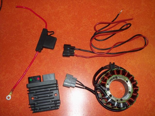
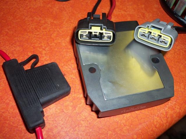
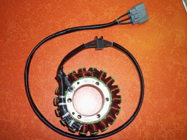
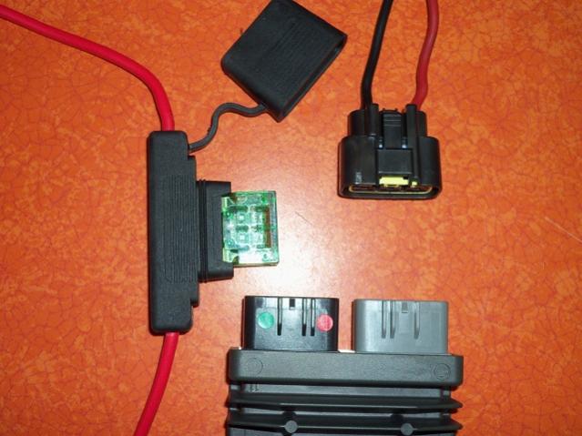
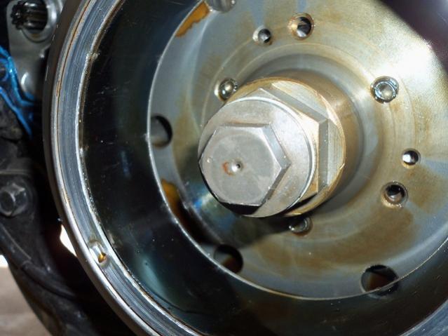
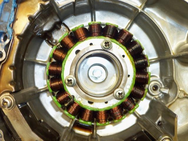
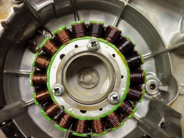
Due to difficulty of reading the technical bulletin in the back of the parts manual in the library, I retyped the two bulletins pertaining to the stator cooling kits. Reddevilmedic with burned coils from 1-7 o'clock, does not appear to be lack of oil cooling mentioned in TA, but please make sure your outside baffel is in place under the inspection cover. The inside baffle on the stator looks correct, but there is no mention of ANY washers. Practice states stator screws are red locktite, and hand impact installed. Also I can't not see the wire (shaft 1) inside the bolt hole, pretty sure I could on mine. Stick a small wire in the hole and feel for shaft 1. 1 final interesting note, is I think I count exactly 6 burned coils, exactly 1/3 of the 3 phase stator. Possible for some reason you have one of the three phases overloaded. As the stator is directly wired ONLY to the regulator/rectifier, this leaves the options for overload limited to the RR ac volt side or the 3 white ac wires. If not already done, I suggest you remove the 3 pin connector between stator and RR. Also do the diode ohm test on your current RR. If even doubtful don't use it on another, 3rd, stator Would strongly suggest to get a clamp amp meter. When you get all back together, test each white wire with clamp meter. They should be about the same amps. Harbor freight has a couple cheap ones should workfor this test: http://www.harborfreight.com/catalogsearch/result?q=clamp+meter 69166.doc 69167.doc
-
Stator...Which One?
bkuhr replied to Wizard765's topic in Venture and Venture Royale Tech Talk ('83 - '93)
Getting my info from back of the parts manuel 1983 xvz12td_k in the libary. Looks like cooling kit is properly installed, but looks like part stator is uncovered by oil level, please confirm the burnt part is on a level line with oil level. -
Intermittant Electrical/Start Issue
bkuhr replied to rayserra's topic in Venture and Venture Royale Tech Talk ('83 - '93)
If the actual glass fuse was getting hot, that would be a very strong indication that the contacts of the fuse were making a 'partial' contact, likely due to corrosion or looseness of the contacts. The heating then is caused by the 'arcing' of the dirty contact. I would be curious as to the actual amp flow across the tail light fuse. 4-1157 low filiment bulbs should draw about 1/2amp each or a total of 2 amps. If for some unlikely reason it was very near 10A, this could cause a hot fuse. Over 10A should blow the fuse, unless wrong fuse in. ( the bright filiments draw about 2.25A each(2 front are turns, 2 rear are brake) but they operate thru a different 'signal fuse'). Place a amp meter set to 20amp scale, and likely probes need to be placed in 20a ports, a remove fuse, and place both probes of meter where fuse was. Tail light should come on to indicate good contact, read the amps. -
The reason for the cooling kit modifications, was to ensure the stator was 100% covered in oil, to prevent overheating above oil temp. Some of the early 83's had part of the startor uncovered, and burned up the copper coils as they overheated. Your 84 should have the kit from the factory.
-
Stator...Which One?
bkuhr replied to Wizard765's topic in Venture and Venture Royale Tech Talk ('83 - '93)
First cool kit mod had a 0.7mm hole with no wire or oil deflectors. Second cool kit mod had a 1.0mm hole with wire inserted from 'inside' the bolt, and added the oil deflector. The bolt with 1.0mm hole also had a punch mark on the head. -
Stator...Which One?
bkuhr replied to Wizard765's topic in Venture and Venture Royale Tech Talk ('83 - '93)
Cool kit was revised 2 times. Second revision included larger hole in the bolt and the wire in the hole to prevent clogging. If you were able to "open" the hole, then I suspect you do not have the wire installed. This could add to your coolong problem. The kit pn was 90891-30014. I found a NOS kit on ebay for mine. -
Intermittant Electrical/Start Issue
bkuhr replied to rayserra's topic in Venture and Venture Royale Tech Talk ('83 - '93)
Please define what you mean by overheating. The tail light circuit is protected by a 10a fuse, and should light the running (marker) (low intensity filiment of dual filiment bulbs) lights on all 4 corners(I think 2 bulbs in brake light housing is the 2 rear corners). Also the 2 rear bulbs operate thru the cmu warning system on the dash. Is there a warning indication? -
Intermittant Electrical/Start Issue
bkuhr replied to rayserra's topic in Venture and Venture Royale Tech Talk ('83 - '93)
A review of the 89 wiring diagram verifies the N.C. contact of the start switch takes out ALL items protected by the headlight 15A fuse, including Headlight Hi and Lo, reserve lighting unit and indicator, dimmer switch and indicator, and all of the panel meter lights. The N.O. contact of the start switch provides a ground to the contacts of the /start circuit cutoff relay/ (internal part of 41R flasher relay). Assuming the other safety circuits(sidestand, neutral....)allow the coil of the /start circuit cutoff relay/ to energize, the grounded contacts apply a ground to the start solenoid coil, allowing solenoid to apply power to the starter. I would expect the start circuit switch to likely be the problem effecting lighting (does not remake contact when released), and possibly the problem with failed start, although more likely for failed start would be one of the saftey systems locking out start. Also do not forget that it is very easy to bump emergency stop switch, which will lockout starter system. -
See them tucked in under the vent duct,under left turn lens. Pay no attention to my modified turn signal flasher (it works with LEDs, no load resistor, and keeps auto cancel. Only good for the 83, as I believe 84+ uses the 41R relay assembly.)
-
stupid question
bkuhr replied to lazy biker's topic in Venture and Venture Royale Tech Talk ('83 - '93)
It was suggested but maybe missed to INSPECT WITH A MIRROR to find the debris that fell down there and is blocking the hole. Depending on what is seen, it may be removed wth a 'hooked' piece of wire, may a stick with gum.......