dingy
-
Posts
5,403 -
Joined
-
Last visited
Content Type
Profiles
Forums
Gallery
Events
Store
Everything posted by dingy
-

Think I misplaced a piece
dingy replied to bkuhr's topic in Venture and Venture Royale Tech Talk ('83 - '93)
Sent email to wrong person, OPPS! Look at link below, it has an exploded view of rear suspension. http://www.venturerider.org/forum/showthread.php?t=1057&highlight=swing+grease+zerks Gary -
Has anyone put a mechanical oil gauge on a 1st gen? Where would be a good place to tap into a oil feed location. I am looking at tapping into the line that comes out of the 'Twinkie' and runs to each cylinder head. Any better suggestion? Gary
-
Think I misplaced a piece
dingy replied to bkuhr's topic in Venture and Venture Royale Tech Talk ('83 - '93)
See this link. http://www.venturerider.org/forum/showthread.php?t=515 Sent you an email with some other pictures. Gary -
Questions about my 83 -
dingy replied to Godlover's topic in Venture and Venture Royale Tech Talk ('83 - '93)
I am going to go out on a limb here and recommend you do not do what Skydoc said in regards to the impact driver. Attached is a picture of the clutch slave cylinder. On the right side is the bleeder screw setting on the long skinny arm. This arm is about 1/2" square and has a hole through it. It is about 1 7/8" long. Aluminum casting. If you hit down on this with a hand impact driver and a hammer with enough force to break bleeder loose, I will put some serious money on the next thing you will be doing is fishing the broken end of that casting out of the bottom of the bike. My suggestion would be to get a 10 mm, 6 point socket. Attach this to a long handle ratchet and somewhat softly, yet firmly, bump the ratchet handle with a hammer. The shock MIGHT loosen the bleeder screw. As best you can hold the socket with free hand to try to reduce the overall rotational twisting action. Do this after letting the bleeder soak in some penetrating oil. I am not an official mechanic, mind you. But I did stay at a Holiday Inn a couple of times. Gary [ATTACH]44065[/ATTACH] -
That is a front fender mount bracket for the brake lines, I think. There is on on each side of the fenders at the point where it mounts to forks. It sets inside of the fender. Gary
-
Attached is a PDF I made for the RSV's showing a trailer wiring hook up. 1st gen's will be the same as far a tying into lights. Gary
-
The butterfly bracket sounds like the one that holds the right and left fairing together at the bottom, under the head light. This is just a guess with out seeing it though. Gary
-
Repack Steering Head Bearings:
dingy replied to Evan's topic in Venture and Venture Royale Tech Talk ('83 - '93)
They are a caged taper roller bearing. Will stay intact. Link to steering head adjusting wrench. (shameless plug) http://www.venturerider.org/classifieds/showproduct.php?product=2747&title=steering-head-bearing-nut-wrench&cat=6 Gary -
Fuel tank sender & petcock pictures
dingy replied to dingy's topic in Venture and Venture Royale Tech Talk ('83 - '93)
Both units have been sold. Gary -
Fuel tank sender & petcock pictures
dingy replied to dingy's topic in Venture and Venture Royale Tech Talk ('83 - '93)
$20 each plus the actual shipping costs. These came out of a 1988 model. Gary -
Questions about my 83 -
dingy replied to Godlover's topic in Venture and Venture Royale Tech Talk ('83 - '93)
The wire coming out of the battery is the acid level sensor. This is tied to a warning icon on the instrument cluster. Try WD-40 or some type of rust buster on the bleeder screw. It's a pain in the rear if you break it off. What tune is it humming?? There are some schematics in the tech section relating to the starting circuits on the bike. Below is the link. http://www.venturerider.org/forum/showthread.php?t=42722 Clutch, side stand, neutral, engine stop switches all involved. Gary -
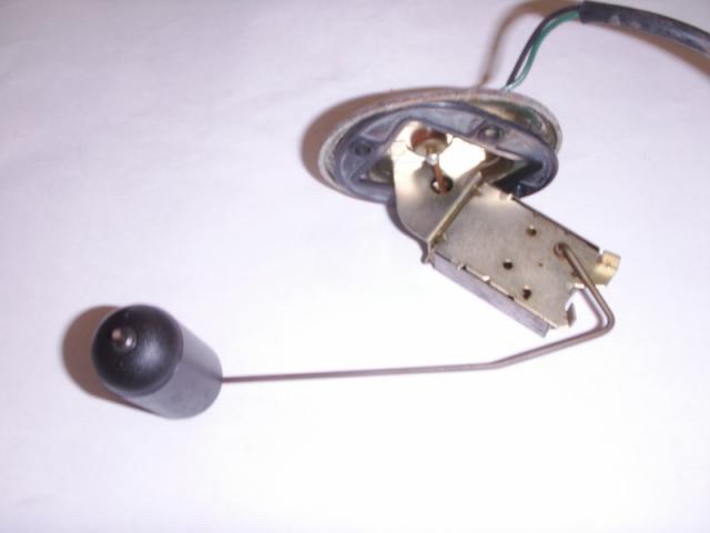
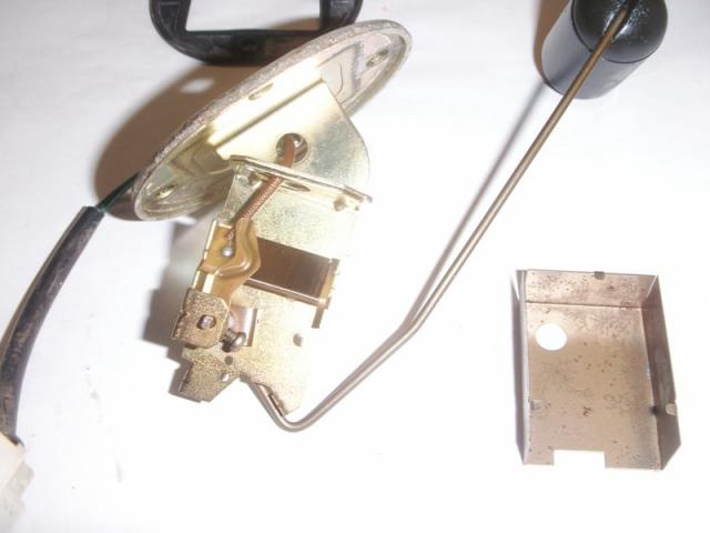
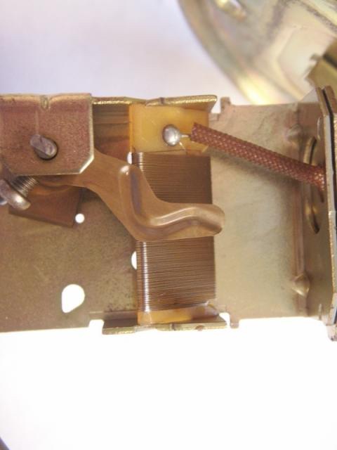
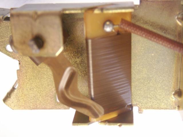
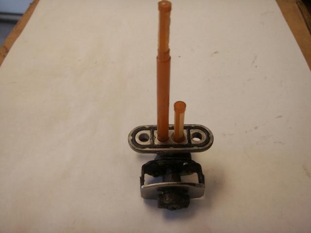
A few posts have been made in the past about the workings of the fuel tank level sender & the petcock. I pulled these parts out of my spare gas tank and took some pictures of them to show how they work for interested members Picture of the sender unit as it came out of the tank. Picture of sender with metal cover removed. The tabs do not have to be bent to remove metal cover. Just spring sides of cover out slightly and cover will slide back. Close up of the wire wound resistor. The metal wiper contact is at middle position in photo. In this view float is all the way down, at the empty position, metal slider contact is now positioned at bottom of wire wound resistor. View of petcock showing adjust lever. View showing the two screens that go into to the tank. The longer pickup tube is for the regular selection. The shorter tube is for the reserve side. Gary

-
Scoot going straight
dingy replied to emtdouggood's topic in Venture and Venture Royale Tech Talk ('83 - '93)
I set just the metal cap on mine, no screws or rubber gasket. It did help. Now just need to reset exhaust valves. Don't think I am going to paint it right away, I want to rid this beast some. Gary -
Scoot going straight
dingy replied to emtdouggood's topic in Venture and Venture Royale Tech Talk ('83 - '93)
Dan's method did help my brake issue. First you will need to bleed the clutch normally though to get the majority of air out. The bleeder screw is on left side of bike above foot peg. It's under a square black rubber cover, about an 1 1/2" square. In my case, the clutch was easy to bleed. Two person job to do this. Gary -
Dingy, still brake trouble?
dingy replied to bkuhr's topic in Venture and Venture Royale Tech Talk ('83 - '93)
I have gotten fairly decent lever pull now. I have tied the lever back to the throttle grip with a zip tie for several days now. Released it in morning and retied at night. But, I can still pull the lever all the way back to the throttle rubber, but with decent pressure. Is this normal with the MKII brakes. I had MKI brakes prior, and I really don't recall how far back the lever came. Could someone check theirs for me please? It's just frustrating with the front brakes, the rear brake & clutch were also rebuilt and they bled first time. Gary -
86 V.R. Bad Carb's?
dingy replied to puppy's topic in Venture and Venture Royale Tech Talk ('83 - '93)
The bad diaphragms I have seen develop very small pin holes around the outer edge. Very hard to see unless a bright light is directly behind diaphragm. Gary -
Every time I get another package in the mail, the divorce gets a little closer. She is even getting a set of passenger floorboards, I thought that would keep her happy, but oh no. Gary
-
Valve Lash using Vmax Cams
dingy replied to GaryZ's topic in Venture and Venture Royale Tech Talk ('83 - '93)
Alrighty then, Shim tool & valve shims are on the way to me. (Thanks MiCarl) Glad I found out about this now before all the plastic was back on. Vmax service manual shows same as Venture in one place,and different in two others. Guess which one I read. Gary -
Vmax valve shim excel spread sheet
dingy replied to dingy's topic in Venture and Venture Royale Tech Talk ('83 - '93)
Try again, I just reloaded it, tweeked error highlighting. Gary -
Based on the finding that Vmax exhaust valves are adjusted to a different setting than Venture exhaust valves I have created a separate Excel work sheet for those that use the Vmax heads. Attached below. The Venture work sheet is in the Tech library at the link below. http://www.venturerider.org/forum/showthread.php?t=43410 Gary
-
Valve Lash using Vmax Cams
dingy replied to GaryZ's topic in Venture and Venture Royale Tech Talk ('83 - '93)
Squeeze, GaryZ's doesn't have the full heads, just cams & springs. Rest of head is Venture with stock valves. Still go with wider clearances? Gary -
Dingy, still brake trouble?
dingy replied to bkuhr's topic in Venture and Venture Royale Tech Talk ('83 - '93)
It got a little better when I tied handle back Monday night. I did it again last night (Tuesday) I haven't messed with it yet. I can squeeze handle to the point where metal lever will touch throttle grip. Is this normal on these MKII brakes? I can pump lever till I am blue in the face and no change. It has always been my experience that if there was air in system, pumping them would increase the pedal (lever) Gary -
Looking for A FEW GOOD PARTS
dingy replied to Dragonslayer's topic in Venture and Venture Royale Tech Talk ('83 - '93)
I have the sensor you need for radiator fan. PM me. Gary -
Dingy, still brake trouble?
dingy replied to bkuhr's topic in Venture and Venture Royale Tech Talk ('83 - '93)
I will try this tonight. Gary -
FJR rear end problem on 1st gen
dingy replied to dingy's topic in Venture and Venture Royale Tech Talk ('83 - '93)
The FJR rear end I had did not come with the spacer it needed. From the parts fiche it does not appear to be a press in like the Ventures use. I had a spare venture rear end that had a spacer in it that was the proper ID, but overall length was a little long and OD of washer was a little big. I have a variety of calipers, depth gauges and bore gauges. I used the rear end that was known to be working OK, which was my original 83 rear end. I measured from face of female hub spline to the top of the spacer. I then modified the donor spacer to match this height when sitting in FJR unit. Gary