Search the Community
Showing results for tags 'wiring'.
-
 Files Updated on 10/28/2009>> All Audio circuits now on main page, so that all schematics are now just one page. Other minor corrections done to all schematics. Text realigned for easier reading Some Line types changed for easier reading. Gary I have completed the 1st Generation schematics. My goal in doing this is to make them easier to read and reduce the number of pages needed to display the information. I have used color and line types to make the wiring easier to follow. In some cases I could not use the exact color that is being represented due to visibility and printing issues. For example yellow is hard to see on the screen and does not print well. The previous posting for the 1983-1985 models have been replaced by what is included with this post. The 1983 differs significantly from the 1984-1985 models in the areas of Flasher, Hazard, Starting Circuit Cut-Out Relays, the Hazard Switch, Canceling Unit & Diode Pack. The files for the 86-89 models that were previously posted have been revised slightly and are now at Revision B. Major corrections done included coils were numbered incorrectly in Simplified Circuit & the Flasher Relay Assembly has been updated to include flasher information. The 1990 major changes from the 1986-1989 models were the TCI, coil pick-up & fuel pump control. This post supersedes all previous posts I have done in regards to the 1st gen wiring diagrams. All 1st gen's are included in this post. The files will look best when plotted at 11" x 17" size or larger. Office Max and Staples as well as others can do this for you for a minimal charge if you want a printout. I paid $1.00 for an 11" x 17" color print at Staples. 83 Yamaha Venture TK Wiring Diagram Rev C.pdf 1983 Venture XVZ12TK From 1983 Yamaha Venture Owners Manual. 83 Yamaha Venture Royale TDK Wiring Diagram Rev C.pdf 1983 Venture RoyaleXVZ12TDK From 1983-1985 Yamaha Venture Service Manual 83 Yamaha Venture TK Simplified Circuit Diagram Rev C.pdf 1983 Venture XVZ12TK From 1983-1985 Yamaha Venture Service Manual, page 7-1 83 Yamaha Venture Royale TDK Simplified Circuit Diagram Rev C.pdf 1983 Venture Royale XVZ12TDK From 1983-1985 Yamaha Venture Service Manual, page 7-1 83 Yamaha Venture electrical info.pdf This file is a compilation of various sheets from the 1983 Yamaha Venture Service Manual that would be helpful when working with electrical system. They are not modified in any way, just as they appear in service manual. 84-85 Yamaha Venture L Wiring Diagram Rev C.pdf 1984-1985 Venture XVZ12L From 1983-1985 Yamaha Venture Service Manual 84-85 Yamaha Venture Royale DL Wiring Diagram Rev C.pdf 1984-1985 Venture Royale XVZ12DL From 1983-1985 Yamaha Venture Service Manual 84-85 Yamaha Venture L Simplified Circuit Diagram Rev C.pdf 1984-1985 Venture XVZ12L From 1983-1985 Yamaha Venture Service Manual, page 7-1 84-85 Yamaha Venture Royale DL Simplified Circuit Diagram Rev C.pdf 1984-1985 Venture XVZ12DL From 1983-1985 Yamaha Venture Service Manual, page 7-1 84-85 Yamaha Venture electrical info.pdf This file is a compilation of various sheets from the 1983-1985 Yamaha Venture Service Manual that would be helpful when working with electrical system. They are not modified in any way, just as they appear in service manual. 86-87 Yamaha Venture DS Wiring Diagram Rev D.pdf 1986-1987 Venture XVZ13DS/DSC From 1986-1993 Yamaha Venture Service Manual, page 8-41. PDF file pages #467 & 468 of 496. 88-89 Yamaha Venture U Wiring Diagram Rev D.pdf 1988-1989 Venture XVZ13U/UC From 1986-1993 Yamaha Venture Service Manual, 1988-1989 Supplement. PDF file page #478 of 496. 88-89 Yamaha Venture DU Wiring Diagram Rev D.pdf 1988-1989 Venture XVZ13DU/DUC From 1986-1993 Yamaha Venture Service Manual, 1988-1989 Supplement. PDF file pages #477 & 479 of 496. 86-89 Yamaha Venture Simplified Circuit Diagram Rev D.pdf 1986-1989 Venture XVZ13DS/DSC - U/UC - DU/DUC From 1986-1993 Yamaha Venture Service Manual, page 7-1 thru 7-4. PDF file page #265 thru 268 of 496. 90-93 Yamaha Venture DA Wiring Diagram Rev C.pdf 1990-1993 Venture XVZ13DA/DAC From 1986-1993 Yamaha Venture Service Manual, 1990-1993 Supplement. PDF file pages #495 of 496. 90-93 Yamaha Venture DA Simplified Circuit Diagram Rev C.pdf 1990-1993 Venture XVZ13DA/DAC From 1986-1993 Yamaha Venture Service Manual, 1990-1993 Supplement. PDF file pages #492 of 496 86-93 Yamaha Venture electrical info.pdf This file is a compilation of various sheets from the 1986-1993 Yamaha Venture Service Manual that would be helpful when working with electrical system. They are not modified in any way, just as they appear in service manual.
 -

wiring 97 palomino edition
Troy meyer posted a topic in Royal Star and Royal Star Tour Deluxe Tech Talk
What wiring harnesses will work on that model and where is the best place cheapest place to find one -
 I recently purchased an Electrical Connection's sub harness, isolator and lighting distribution block for my 2018 Yamaha Star Venture. The reason I purchased this was to install an under glow kit with brake and turn signal functionality. For the turn signal feature of the under glow kit the lights turn amber and blink (only the side that corresponds with the turn signal the other side turns off). For the brake feature of the under glow kit all lights turn to red when the brake is applied, once the brake is released the color reverts back to the selected color. I have followed the installation instructions for the sub harness, isolator, and lighting distribution block. Once that was installed I connected the under glow kit using the "accessory light wiring" section of the lighting distribution block installation instructions. The initial results are as follows: When the bike is off the color of the under glow kit is green, which is the selected color. When the bike is turned on the color of the under glow kit immediately turns red, as if the brake has been applied. Also the turn signal feature does not work at all. In trouble shooting, without the help of a multimeter or test light, I have found the following: If I disconnect the blue brake wire on the under glow kit from the lighting distribution block then when the bike is turned on the color of the under glow kit stays green until the turn signal feature is engaged at that point it works as desired. The lights turn amber and blink (only the side that corresponds with the turn signal the other side turns off). Once the turn signal is disengaged then the color reverts back to green. To make sure the blue brake wire of the under glow kit was not the issue, I hooked it into the left signal side of the lighting distribution block. This was the result: When the bike is off the color of the under glow kit is green, which is the selected color. When the bike is turned on the color of the under glow kit stays green until the turn left turn signal signal feature is engaged at that point it works like this The left side lights turn red and blink. Once the turn signal is disengaged then the color reverts back to green. This tells me that the blue brake wire to the under glow kit is fine. My thought is that the lighting Distribution block has constant power coming in on the blue brake wire. Following that line of thought I am wondering if the front brake switch, which I received a recall notice on is truly faulty and causing this. I am awaiting a multimeter to get more detailed data. I would like your thoughts on this, any assistance would be appreciated.
 -
In the process of wiring up my new Polk 401 speakers. From what I have read the rear speakers are only mono. Has anyone rewired the rears for a true stereo sound? Can this be done? Everything is apart so I can run new wires to the rear, bypassing the stock wiring. Thanks for any info.
-
Tech wiring question: I just bought a used Kriss headlight modulator and it modulates on low beam. I'd like to switch this to high beam but not sure how, especially since one end is plug and play on the bulb. Anyone know?
-
I’d like to make a headphone adapter that will allow me to plug a 1/8 stereo into the factory headset plug on a 2nd Gen for music listening. I’ve got a noise reduction headset that I’d like to install in my helmet and plug directly into the bike. My thoughts are that if I get a male adapter and the 2nd Gen and the wiring diagram for the headset plug that I could make an adapter to a 1/8 female stereo plug. This (I hope) would allow me to plug in the noise reduction headset. Can it be done and do you think it will work??? Secondly, does anyone have the wiring or schematic diagram for the headset plug that shows what each pin is for?? Charlie
-
 All, I bought a new (Harbor Freight Tag Along) trailer to tow behind my 1986 Venture Royale. Trailer has 1 wire for running lights, 1 wire for right brake light AND right turn signal, 1 wire for left brake light AND left turn signal and 1 wire for ground. The trailer I had been borrowing had 2 wires for the turn signals (right and left) and one wire for the brake lights , one for running lights and a ground wire. If I try to run a turn signal and brake light on the same wire I'm not so sure it will work, because my '86 uses a separate wire for each turn signal. Do I need to rewire the trailer or is there an adaptor device that will allow me to keep the stock trailer wiring and not fry my bike wiring? Thanks for any advice you can give. Bob
 -
Anyone know where I can get a look at a wiring diagram for 1st Gen audio system? My cassette deck has gone AWOL and would like to remove it and wire in a stereo connection to plug in my IPOD, but the wiring diagrams in the manual seems to have identified every wire except those from the deck to the amplifier. Appreciate your help.
-
 Part 1 of 4 ? Hi there, so this write-up is about our Venture Royal, the work behind it, what it took to not just get her back to running condition, but rather get her back to the responsive touring bike I’ve read (had yet to experience) she is! First things I did was try to ready it the 1st season for a short trip up and in BC with my boys. I went through the wiring one plug at a time; things seemed to be in pretty good shape! What I like about doing this with a “new to me bike” is that it formularises me with the systems and what might go wrong, where it is located and in a pinch if need be, I can sort through a problem quickly while on the road! Next I move on to the brakes and suspension, here is some of what I did: Drained ALL the hydraulic fluids- brakes, clutch, forks, and “fork air lines” Chained out the front springs with some I had from another project Changed the brake pads front and rear Change the dif oil, Changed steering stem bearings Disassembled the air control panel, cleaned with contact chemical Replaced burnt lights and fuses Replaced the tires Changed out the handle grips for 1” rubber/chrome type, I need the larger grips as my R/hand is a rebuilt unit. Some 30 years back I had a one on one with a hydrant;( You know they said it was my fault? Even though I assured them I wasn’t the fool that placed it there? Hydrants go on the inside of a bend! Not the outside of a bend!( Lubed the drive shaft spline with synthetic grease- I have come to respect the synthetic grease for each application where grease is called for; it stays put, stays bright in color, resists washing out- even when exposed to solvents, and in my experience maintains a cooler bearing, and also important is that it remains consistent- I add it to all my replacement bearings with an epoxy syringe! Took it for a ride, I found on the Mountain roads when the suspension was properly set and with 2 up and camping gear she could sweet talk a twist very well; however I was disappointed in the thrust! SG/Patch's
 -
 I plan on installing an aftermarket stereo. Looking for a how to for wiring it. My factory radio/cassette work fine, but only one speaker works and just doesn't have the sound quality I would like. I saw a 4x6 speaker install that I also plan on copying. My bike came with a blank that goes in place of the stereo which I plan on installing an aftermarket head unit in place of the stocker that I remove.
 -
well i have a 750 that the wiring harness had to be replaced. took old harness out and was putting newer one in. cant remember where all the wires in head lite bucket goes. any one have a picture of theirs. the wiring diagram i have stinks. will take all the help i can get. been buying parts here and there to put it back together. as caught on fire. been at it for a year now. have time to wire it now.:think::think: HELP lost
-
I've seen them on here before but can't find any. Does anyone have a color wiring diagram for the RSV? specifically the lighting section. Had to do some work on the brake lights on mine and found that the PO royally screwed stuff up back there. I'd like to go back to square one and start over. thanks
-
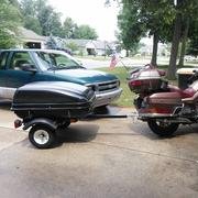
and side lights for trailer today... didn't like the standard lights not bright enough...$39.00 @ HF for tail lights, side lights & wiring (which i didn't need, oh & license holder)
-
Buddy has a 2006 RSV with a 4 pin wiring harness, He is wanting to pull my Bushtec trailer that has a 6 pin. Does anyone no of a converter or should I just tell him to order the harness from Bushtec? Anyone with a sugguestion? Thanks
-
Can someone show mw a picture of where the wiring harness is under the seat, or am i best to hook up behind the lisence plate?
-
 Just received the Signal Dynamics Light Bar and have a wiring question. My RSV already has the LED light/spoiler on the top of the trunk (I think it is an OEM accessory) and I traced the wiring from that light under the seat and up to (or past) the battery. My question is this, I can either strip some insulation on existing wiring under the seat and solder the light bar wiring to it or I could cut the wires and put in a couple spade plugs (and seal things to keep out moisture) to allow easy removal of the trunk if needed. Any advantages to either method? I'm guessing either one would work but want to get the thoughts of those that have a better handle of electrical systems. Thanks!
 -
Ok, I found the first problem: I was realizing that the right turn panel light was blinking faster than the right one when after check that the lamp on front was lighted but not blinking. It was on due to the position, but the second filament didn't not power on. I assumed that was the bulb (I didn't saw the filament broken but it could be the contact) so purchased a new one, but still the same. So, since I never followed this wiring on the VR is something special to take care looking for this problem? Anybody had this problem before? :sick::sick::sick::sick::sick:
-
When my bike was imported new to the Uk, the turn signals had to be changed so they only flash when turning & then are off. But I know from your bikes & my previous 'Wing, yours are on all the time. Do any of you know how this is done? Is it by the wiring, if so where would it be, or by a special bulb or something. Greatful for all your knowledgeable help.
-
Did this on the Wing so posting here ... The dilemma I was facing was how to put together a nice, clean, somewhat out of the way wiring connection for the trailer. Different hitches might present a different way of doing this but the design of the Rivco hitch doesn't offer much for possibilities. So, I figured I could install a "flush mount" type round plug underneath the trunk, next to the side bag and trunk release levers. As I had already installed a trailer wiring isolator kit designed for plug-and-play at the back of the bike, it was just a matter of taping into the wiring coming out of the isolator. Here's pics of my install... Product Used... [ATTACH]68744[/ATTACH] Backing Plate... [ATTACH]68745[/ATTACH] Wire Routing... [ATTACH]68746[/ATTACH] Marking for the holes using the metal template... [ATTACH]68747[/ATTACH] All cutout and ready for the plug... [ATTACH]68748[/ATTACH] The plug from underside of trunk bellypan... [ATTACH]68749[/ATTACH] The inside of the plug waiting for wires... [ATTACH]68750[/ATTACH] All wired up (had to use same color wire coz I didn't have others but that's no problem) [ATTACH]68751[/ATTACH] Finished Product ... male connector yet to wire up. [ATTACH]68752[/ATTACH]
-
I have the left front lower off, checking the fuses ( there good) what's the black box above the fuses? with two sets of wiring coming out?
-
Riding home from a 170 mile ride this afternoon, the radio started cutting out, as I hit the back brakes. I made it to a gas station, filled up and no start. so I checked all the wiring, No lose battery bolts, nothing grounded that i can tell. and the battery is some what new. Throw some Idea's at me, please.
-
Just finished wiring the beast for a trailer using a Reese Towpower tail light converter. Bike lights behave normally after completion. When I connect the trailer and turn the key the headlight fuse blows. I see two possibilities: 1. There's a short in the running lights on the trailer or 2. The trailer running lights are too much draw for the circuit. Any helpful thoughts appreciated...
-
I have never been satisfied with the tail/turn/stop lights on my Harbor Freight trailer. I had changed the bulbs to LED's, but just not enough illumination, especially in the day-time. These were about $16.00 each at Wally-World. A bit of a challenge to mount, but I stuck with the measure twice, cut once rule. Well, I also cut the holes somewhat undersize then shaped them to fit the template I had made. Pretty much labor intensive, but I think the end result was worth the effort. I completed the install with wiring and connectors that I already had. I now have (additional) stronger lighting, located to be much more noticeable. I have some tidying up to do on the wiring, but it's basically completed. Pic 1- rough cut for left light (took a lot of patience and elbow grease to finish) Pic 2- some of the tools and "stuff" I used Pic 3- Hooked up with running lights and left turn signal on
-
Hi All, Added a few new parts to my new (to me) 96 Royal. Cobra drag pipes, Corbin Solo Seat, Barons Star Bars, Kuryakyn Curved lighted licence plate holder, Barons Ultimate Light Bar and rear fender rack. I am happy with the new parts but as always there is more to do. Next is internally wiring the bars, blacking out and polished fins on the engine covers, tacho, braided lines all round, bigfoot mod and Dyna ignition. Ahh, so much to do....so little money.
-
This seems to be the correct forum to post this request. (If not, I apologise - so just respond, okay?) Seriously though folks, I have fitted a Voyager outfit to my 2004 RSV and now need to hook up the additional lights fitted thereto. The Voyager is obviously wired up, with a 7-pin flat plug and I have acquired the matching socket and cable to wire in to the bike. I've been told by other 'Voyagers' that the best place to do so is just aft of the battery. I would assume that would be correct, and I would just use normal 1-into-2 splicing connectors? I'm okay with doing it myself, having dabbled in auto wiring (and house wiring) for many years. The other option is to go to the harness and connectors beneath the tail light - the ones all curled up under the number plate bracket. Any clues, ideas, opinions and/or advice please? Thanks for your collective time. I know it's valuable.