dingy
-
Posts
5,403 -
Joined
-
Last visited
Content Type
Profiles
Forums
Gallery
Events
Store
Everything posted by dingy
-
These fuses are only energized when key is in RUN position on an RSV. I don't have the RSTD schematic. But they should be some what similar as far as fuse functions. You could tap of off any of them to energize a relay coil. Ignition Cruise Fan Carb Heater Signal Gary
-

Not starting after new cams installed
dingy replied to GaryZ's topic in Venture and Venture Royale Tech Talk ('83 - '93)
Then, no it is not a clearance engine. Gary -
Small Electrical Problem on 93
dingy replied to Big Hack's topic in Venture and Venture Royale Tech Talk ('83 - '93)
Is it only blowing when you use lighter, or is it blowing when lighter has not been used. If only when lighter has been used, possibly a bad element in lighter. If lighter has not been used, then find the short to ground in the positive lead between the fuse and the lighter plug. 30 amps is a bunch of current. That is more than the equivalent of 7 headlights worth of current It would almost have to be a short if you are using this outlet to power a GPS or other electronic device. Gary -
Not starting after new cams installed
dingy replied to GaryZ's topic in Venture and Venture Royale Tech Talk ('83 - '93)
WTF is a clearance engine ? There is a lot of clearance between the back end of a 1st gen and the front end of a 2nd gen when racing I guess. Gary -
Not starting after new cams installed
dingy replied to GaryZ's topic in Venture and Venture Royale Tech Talk ('83 - '93)
I am not saying your wrong Brad, but I just had an engine apart and when I tried to even re-shim valves without an official valve tool, I had to release the cam tensioner in order to get enough slack in the chain. The purpose of the tensioner is to remove all the slack so there is no slop in chain. The tensioner is a one way ratcheting mechanism, it has to be pulled out of the engine in order to release the tensioner rod holding prawl. Even if he unbolted the gear from the cam, as soon as there is any slack in cam chain the tensioner is going to extend via its spring, then making it impossible to reattach gear. Just my humble opinion, but I did stay in a Holiday Inn a couple of times. Gary -
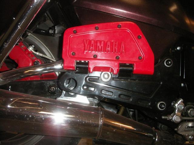
The top pair of plugs in the first image attached is from a bike without a CLASS system (Computer Leveling Air Suspension System). Note the connector on the top right is a 2 pin plug. The bottom pair of plugs in the first image is from a bike with a CLASS system. Note the connector on the bottom right is a 3 pin plug. This extra pin is to power the class system when key switch is in ACC position. Second image attached is of the contact plate on the set with CLASS. This contact plate and wires can be swapped between key units. I just did this on my bike. I wanted to keep the same keying, but had swapped wiring harness's & added a CLASS system during the rebuild this winter. Gary
-
Not starting after new cams installed
dingy replied to GaryZ's topic in Venture and Venture Royale Tech Talk ('83 - '93)
Please say that you cranked engine over by hand through several revolutions first !! Gary -
It will if the 84 that it is coming out of had the class system. The class system equipped bikes have a 3 conductor plug for the 'auxiliary' wires. Non class bikes have a 2 conductor plug. You can make the switch work either way, but you would need to dis-assemble the bottom and swap out the contact plate. The internals are the same. I can send you pictures if you get the switch and need to modify it. The tumblers can be swapped out by a locksmith fairly easily, I believe. To do it yourself you would need the key to pull the tumbler cartridge out. There is a small ball & spring in there that is a pain to put back in. Gary
-
Not starting after new cams installed
dingy replied to GaryZ's topic in Venture and Venture Royale Tech Talk ('83 - '93)
Can you reach rear cam tensioner. You will need to remove it, Then reset cams, Then reinstall tensioner. It sets between the rear exhaust headers. If you can get tensioner out, it is doable. Also be careful when reinstalling tensioner. I had one of the wings break of on my front head causing an initial oil leak. Torque down by going back and forth several times. Might also need a new gasket for tensioner. I ended up making one. Gary -
If you used MKII floor boards, It seems you would have had to do something to the rear exhaust mount. In the picture attached to this post, the large rear hole on the frame mounted foot board piece is where the mount for the muffler should have been. It does not line up though with the stock MKI mufflers. Not saying yours didn't work, just that mine needed the rear mount modified. The new hanger can be seen behind the black part of the floor board. Gary
-
These are shown on an 83 now. Gary
-
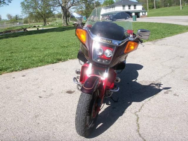
It has a LOT more acceleration. I can pop the front end up fairly easy now. Red line is now close to 9000 RPM's. Seems like I need to upshift when I am in 5th though due to FJR rear end, it will take a little getting used to the higher cruising RPM's. As far as the brakes, I am happy at this point. The rear will not lock up on me which is good in my opinion. The fronts will lock up, which could not be good, but will be same as bikes I have always rode. I also made a revision inside of the wiring harness to keep the electric anti dives from engaging when only the rear brake is used. I have heard the electric A/D's are energy hogs. Didn't figure I needed them when I was only using rear braking. This way, if I am in traffic, I can use the rear brake and not have the drain on the electrical system. Gary
-
Not starting after new cams installed
dingy replied to GaryZ's topic in Venture and Venture Royale Tech Talk ('83 - '93)
Besides what Bkuhr said, another guess could be exhaust & intake cams swapped. Gary -
Here is a link to a set in the classifieds. They are missing one rubber & need serious cleaning / sand blasting. The ones I posted pictures of above didn't look much better though in the beginning. http://www.venturerider.org/classifieds/showproduct.php?product=2685&title=rear-footboards-mkii-1st-gen-venture&cat=6 Gary
-
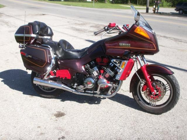
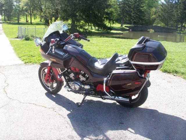
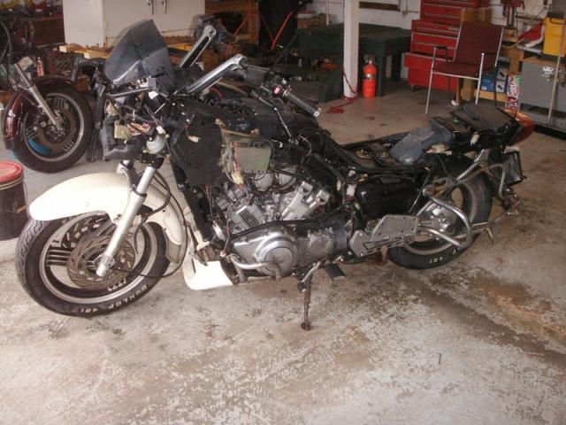
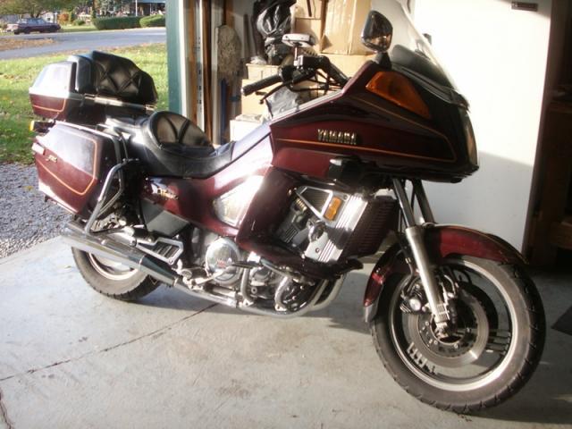
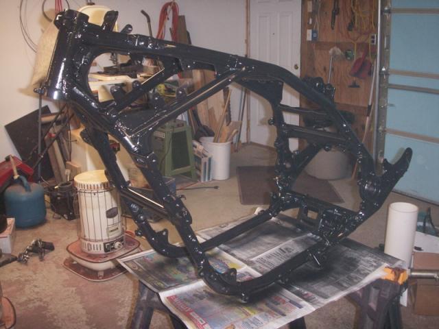
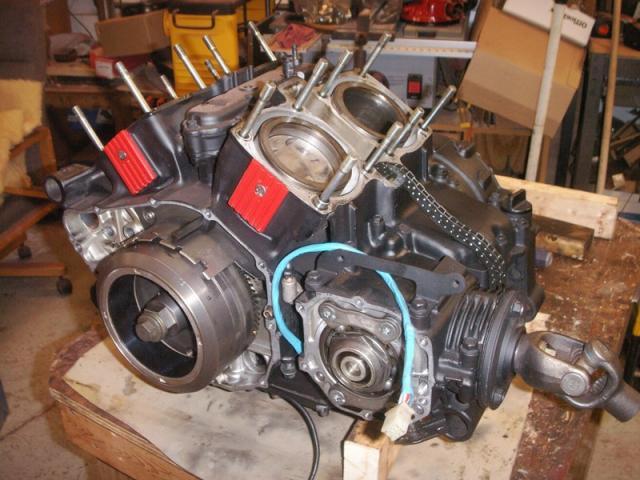
My re born 83 had its coming out party today. It is finally all back together. There are parts from 3 different decades on this bike. It will be a different color next spring. Probably a bright blue or yellow. Thanks to everyone that contributed knowledge and parts to get this done. Below is a list of the major improvements this winter and a few pictures of it. 1300 engine, 1988, 28,000 miles Vmax Heads, 1997, 19,000 miles FJR rear end, 2004, 7,000 miles MKII front forks, 1986 MKII brake calipers & rotors - front & rear MKII brake master cylinders - rebuilt Delinked brakes Stainless steel brake lines Speed bleeders Kevlar brake pads Electric Anti Dives – only operate on front brake Rebuilt clutch master & slave cylinders Stainless steel clutch line set Two diaphragm springs in clutch Replaced half clutch plate with full plate Starter ground upgrade 8mm ignition wires Iridium spark plugs K&N air filter Crankcase air breather filter Re-jetted mains to 140 Shimmed needle jets to .072” Updated rear shock to one with spring Grease fittings added to shock linkage Halogen Dual Projector Headlights Added tail light bulbs to rear turn signals Cruise control Class system Royale instrument cluster 1988 wiring harness Changed radio to AM/FM CD player 3 way speakers in front -Tweeters in saddle bags Shorty antenna Relocated TCI to radio compartment Radar detector & GPS mounts Bikini side covers Polished case covers S.S. bolt set for side covers Passenger foot boards Moved backrest rearward 2” Powder coating Pictures today. Started out as this. Went down to this. Donor of lower engine and brakes.

-
Attached are a couple of pictures of a set of 86-93 rear floorboards. These require a very minor mod to the rear exhaust mounting. Gary
-
Click on the 'Listen.M3u' download again. It restarted for me. Gary
-
"Thanks" Has Stopped Working
dingy replied to Aussie Annie's topic in Computer help and tips for using this site.
Thank You, Thank You very much !! In my best Elvis voice Gary -
"Thanks" Has Stopped Working
dingy replied to Aussie Annie's topic in Computer help and tips for using this site.
You appear to very Thankful Gary -
Working real good. 9:20 PM est Windows Media Player Gary
-
Electrical: Fuse question
dingy replied to TomMar's topic in Royal Star Venture Tech Talk ('99 - '13)
That doesn't apply in this case. Ohm's law is not involved in a voltage rating for a component. 1 amp of current flow is the same regardless if is at 12VDC or 120VDC. The circuit resistance would be increased by a factor of ten due to the 10 fold increase in voltage. But an amp is an amp at any voltage. Current flow is a measurement of electrons flowing past a point in a circuit. This flow of electrons creates heat. This heat is what causes the fused link to melt and open the circuit. Gary -
Which wife is it that you are wanting the help with. Both were in the thread. http://www.venturerider.org/forum/showthread.php?t=44005 Gary
-
Electrical: Fuse question
dingy replied to TomMar's topic in Royal Star Venture Tech Talk ('99 - '13)
You can safely use 10A/125V fuse in place of the 10A/32V fuse. The voltage rating is a maximum value that the fuse should be operated at. It does not change the current value of the rated fuse value. Gary -
The white wire goes to the TCI unit. It is the trigger wire for coil # 4. Each coil has a separate circuit to the TCI. The Red/Black wire is positive battery that is connected to each coil. The coil is normally energized. If key is on , there should be 12 volts present on the Red/Black wire and each trigger wire to the coils. When the spark plug fires, the TCI removes the trigger (ground) to that coil. When the trigger is removed, the coil field collapses, causing the spark plug to fire. Tachs read this pulse on the coil trigger wire and convert this info into an RPM display. Gary
-
1 3/4" was in 2nd gear Closer to 2" in 1st gear Gary