dingy
-
Posts
5,403 -
Joined
-
Last visited
Content Type
Profiles
Forums
Gallery
Events
Store
Everything posted by dingy
-
Mohican State park is a great place to ride. I live about 20 minutes from there and like to go riding around there. Especially the two roads that lead down to the covered bridge. Gary
-

no power to fuel pump
dingy replied to Mikel_NY's topic in Venture and Venture Royale Tech Talk ('83 - '93)
Below is a chart from the 86-93 service manual showing normal fuel pump operation. Also shown is fuel pump relay testing cut from manual. 83-85 bikes are essentially the same, but the 83-85 manual does not have a as good of a write up. The fuel pump will be powered up when you turn the key on. In about 5 seconds, if the engine is not running it will shut back down. What this means is you need to have a meter connected, so that when you can see it, then turn the key on and see if the unit gets power for 5 seconds. There is some electronic circuitry inside of the fuel pump relay that contains a timing circuit. It senses the firing of the #2 cylinder and keeps the relay energized when the bike is running. It shuts the pump down if bike is not running and key is on. The 83-85 is essentially the same as the 86-93 setup but they have a separate control module for the fuel pump relay. Gary http://i1007.photobucket.com/albums/af193/gdingy101/fuelpumpchart.jpg http://i1007.photobucket.com/albums/af193/gdingy101/fuelpumptest.jpg -
Won't stay running
dingy replied to Chop's topic in Venture and Venture Royale Tech Talk ('83 - '93)
A small addition here, do not remove this panel with a full tank of gas, it needs to be below 1/2 tank full. Fuel will run out of panel when it is loosened if tank is full. Gary -
Researve lighting unit
dingy replied to Flyinfool's topic in Venture and Venture Royale Tech Talk ('83 - '93)
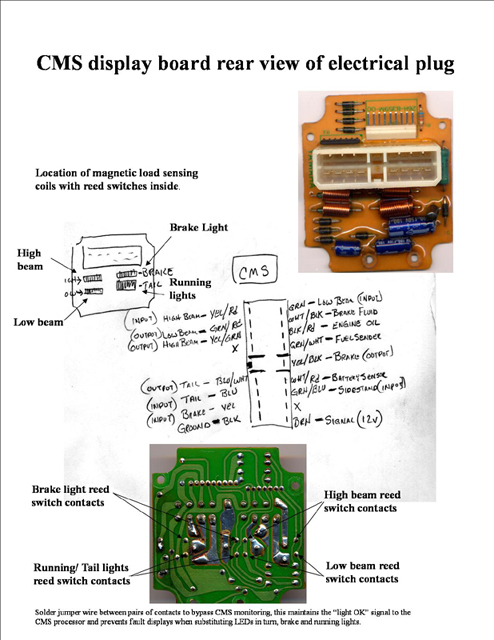
Here is a picture of what you need to do to stop CMU warnings. I believe Saltydog made this up. The reed switch contacts on the high & low beam circuits need a jumper soldered across them on the non-component side of the board. Please note that this info pertains to a non-royale style of CMU. Gary
-
What do I put in here?
dingy replied to VentureBob's topic in Venture and Venture Royale Tech Talk ('83 - '93)
Looks like it might be a Vmax to me. You can see where the shock bolt was cut off and ground down in right of picture. Gary -
Aftermarket TCI available!
dingy replied to tvking63's topic in Venture and Venture Royale Tech Talk ('83 - '93)
You can use a TCI from 84 through 89. The attached picture shows a red arrow pointing to one of 8 diodes. They are all the same and lie in approximately a line straight up. A 1N4001 or higher diode can be used. Gary -
Aftermarket TCI available!
dingy replied to tvking63's topic in Venture and Venture Royale Tech Talk ('83 - '93)
Here is some info on what I have done so far with the module. I had a phone conversation with TVKing63 and some PM's back and for with Squeeze, both have helped me get to this point. One of the problems that I was having is the output voltage of the GM map sensor that I am using is just a little over 3.0vdc at idle. The Ingitech software has a high end hard coded threshold of 2.5 volts at idle. With some trial and error, I found that if a 250K ohm resistor is put in series between the output of the map sensor and the input of the Ignitech unit, the idle voltage will be approximately 2.0vdc. By doing this the full range on the Ingitech mapping curve can be utilized. Prior to putting the resistor in, I was unable to use anything below about 30% vacuum advance. Now I am able to start at the 0% bracket. The next issue I was seeing, and it may not be a major one, was the pulsing of the vacuum curve at idle. TVKing63 indicated he was seeing the same thing but he thought it smoothed out alright above idle. The solution that I came up with incorporates two ideas from previous posts in this thread, with a third added. Somewhere, and I can't find it, someone had mentioned tying all 4 vacuum ports together to smooth the curve. This is the first thing I did. Second was to get the inline restrictor that TimGray had used. The third thing was to add a small canister to the vacuum line going to the map sensor. I used a piece of 2" PVC, just long enough to be glued in place between two PVC caps. In one of the caps, I epoxied in two 3/16" plastic air nipples. There is an upside and a downside to the canister idea. The upside is that it will smooth out the pulsing. The downside is that it will induce a lag into the throttle response curve. The reason that the canister so short is to reduce this throttle lag. A smaller diameter canister may still work, but this was the path I was on. Squeeze suggested I use an RC timing circuit, which consists of a resistor and capacitor in parallel, to smooth out the pulsing. This would be a more compact solution, but for now I am satisfied with the canister. There are two videos that I put on You tube next that show the difference without & with this canister. First one is without the canister, notice the blue bar, which displays the TPS (Map sensor) voltage. It is varying quite a bit. Both of the video's were taken with the TPS threshold set lower than optimal, so the bouncing would be evident. [ame=http://www.youtube.com/watch?v=wqhoGqGE4_A]YouTube- TP wo can[/ame] Second one is with the canister inserted in the line. Now the TPS voltage is much more constant. [ame=http://www.youtube.com/watch?v=ghQNJn23sAo]YouTube- TP w can[/ame] Next video shows screen views with the engine being reved to display TPS response. I believe I will lower the upper threshold of the TPS voltage from what is shown in this clip. [ame=http://www.youtube.com/watch?v=u3K3CKEMxvA]YouTube- Map w can [/ame] Picture next is of the canister. [ATTACH]48709[/ATTACH] Next is one of the fitting I found at O'Rielys that I tied the four vacuum ports together with. Part number is Dorman 47361 [ATTACH]48710[/ATTACH] Next is one of four vacuum ports tied together. [ATTACH]48711[/ATTACH] Next is of all three components to Ingitech system I am using. [ATTACH]48716[/ATTACH] Lastly is the software curve I am using. I downloaded and tried TVKing63 latest map 'Venture 11e 2500-4500TPSV.ign' This one seemed to be lacking some throttle response. From what I have researched, it seems that full vacuum advance is not useful at WOT. This is based on article referenced next. This is of course just one opinion on the matter. http://www.thesavoy.de/html/vacuum_advance.html Squeeze sent me what he thought would be a good starting point for a map. I tried it as he suggested, but there was a distinct hesitation when going from a steady 4500-5500 RPM to WOT. I modified his curve by pushing the advance out farther and this cleared up the hesitation. Below is a screen shot of TVKing63 3D curve and Map. [ATTACH]48712[/ATTACH] [ATTACH]48713[/ATTACH] Below is shot of what I am trying for now. [ATTACH]48714[/ATTACH] [ATTACH]48715[/ATTACH] Which style of mapping is better can be best measured by a dyno, which I hope to do this fall. The previous one I did was a low cost one at a shootout. I did not get torque values or A/F readings which will be very useful to guide me in what to do to get some decent HP out of this bike. Gary -
pickup coil info / help
dingy replied to bald josh's topic in Venture and Venture Royale Tech Talk ('83 - '93)
That fairly closely matches up with the 84 parts fiche. Depends what year he had. If you don,t have one, PM me your email address and I will send it to you. Gary -
No, I have not completely interchanged dashes. On my 83, when I put the 88 wiring harness in, I used an 88 dash. I did swap out the speedometer head & tach in order to maintain the correct mileage on the bike. I did the tach due to the markings on the face are different from MKI to MKII's. But I did use the 88 CMU. I have had an 84 wiring harness, which did have the correct CMU connectors for the Royale dash. This is what leads me to believe that the CMU units from an MKI are the same as an MKII. I looked in the parts fiche and it only lists part numbers for the Royale dash, I do not see listings for the standard dash in order to compare to an MKI. I specifically looked in the 88/89 version as I am almost certain was offered with the standard or Royale dashes. I do not see in the fiches where a standard part can be ordered in lieu of an upgraded part. I am almost certain that there were MKII's in 88 & 89 that had the standard dash in them. This was the model XVZ13D. The XVZ13DU had the Royale dashes in them. I am not aware of any 83 dashes that were the Royale version. 84 & 85 models were XVZ12L, standard dash and the XVZ12DL which had the Royale dash. 86 & 87 only show the Royale model XVZ13DS, which all had the Royale dashes. 90-93 models were only the Royale version, model XVZ13DA. All of the above models are a result of what I learned when I did the wiring schematics, which may be wrong. I did do a version of the schematic for an 83 showing a Royale dash, which I now know was not a stock production model. At the time , I thought the XVZ12DTK model had the Royale dash. The XVZ12K was the stock model. Due to finding the wiring connector difference I noted in a previous post, you are correct saying that an MKI Royale dash will not be plug-n-play in an MKII bike. It would at a minimum,require swapping out the wires in the plastic connector on the MKI dash head to the one in the old MKII dash head. You are also correct that there are many more MKII dashes available, might as well get the one that will fit right in. Gary
-
I do see the difference in the wiring now. Due to the cruise light there is a six pin connector (5 used) to the cluster lights on the MKI's On the MKII's this is a 4 pin connector, since the cruise light was omitted. My bad. Gary
-
First picture is an 83 dash. Below is a picture of an 89 standard model cluster. XVZ13U model. The XVZ13DU had the upgraded royale cluster. There are different markings on the face of the tach and speedo on the MKII's, also the MKI's had the cruise light in the face of the tach. That may be the only difference. Gary http://i1007.photobucket.com/albums/af193/gdingy101/120509024.jpg
-
Do you know what is different. From the wiring diagrams, they look the same. Below is a picture of a Royale cluster from the 83-85 service manual (supplement). Top caption says XVZ12DL. Gary http://i1007.photobucket.com/albums/af193/gdingy101/MKIroyalecluster.jpg
-
Edit to this post. Due to a wiring connector change the MKI dash does differ slightly from an MKII dash. See post farher down for better description. Gary An MKI from a Royale should work if the existing unit is a Royale. I don't think there are any differences. The non Royale units have totally different cable connectors. It is a Royale dash if it has the clock/timer display at the bottom. First picture below is a standard unit. Second picture is rear of standard unit. Third picture below is a Royale unit. Fourth picture is rear of Royale unit. Gary
-
clutch issues...again!
dingy replied to Trader's topic in Venture and Venture Royale Tech Talk ('83 - '93)
Bleed it again, I like the synthetic brake fluid DOT 3 or 4. It is not nearly as harmful to paint as regular fluid, and it is less disposed to absorbing water. After you have it bleed, take a zip tie and tie the clutch lever back all the way back against the grip. Loosen the cap and rubber so air can get in to the master. Leave it this way over night. You may need to do this a couple of days. Don't ask me how this works, I just know from experience that it does. Gary -
That would seem to indicate you have plugged idle circuits in the two carbs. Seafoam it very heavy, like a half can in a tank that is less than half full. Ride it hard for an hour, then let it set for a day or so. Run the rest of the tank out. Fill it with 89 or better about half full and put the rest of the seafoam in and ride it hard some more. You can get seafoam at wal-mart and autozone for sure. It's about $9 for a 16 oz can. Gary
-
pickup coil info / help
dingy replied to bald josh's topic in Venture and Venture Royale Tech Talk ('83 - '93)
Try sucking on the hose that goes to the vacuum sensor. Seriously. If you can draw air through it, then it has gone bad. I have one that did this. I don't know why that would cause cylinder not to fire, but it is something to check. Gary -
I am having a slight drip out of the left side on mine also. Sealing washer on bottom of middle drive cover was dry. Drip is forming on floor an inch or so ahead of bottom bolt on middle drive cover. I thought I might have a leaking side cover gasket, so I got new ones for stator and mid drive cover. When I pulled covers off, it was dry as a bone in behind middle drive cover. No leaks around gear indicator, shift shaft or stator & pickup wires. Cleaned surfaces, no cracks or nicks found. Coated both sides of gasket with sealer, which I will regret next time I need to pull them, and replaced covers. I still have the drip. Next culprit may be a leak in the oil pan. Or possibly a loose case fastener. Doesn't always drip just once in a while. Enough to be a source of irritation due to the ribbing from my Harley friends. This coincidentally started around the time when I put the Harley drivers backrest on the bike. Might be a virus. Gary
-
I got an email from patch guy today and he said he would give me a price break on 20 of them considering he would not have paypal, ebay and shipping and handling fees on each one. I will probably get 20 of them from him if there is enough interest in them and pass them on to people that would want one (or more). He said it would be 2 or three weeks. They are 3 x 4 inches in size. Gary
-
starting problems
dingy replied to Greg Kendall's topic in Venture and Venture Royale Tech Talk ('83 - '93)
This topic has been discussed several times here before and it is almost as varied as oil and tire topics. Ventures use a Shunt type regulator. This style regulator discharges excess current coming from the stator to ground via an electronic circuit, probably large SCR's. This shunt system is designed to handle the expected output of the bikes stator which is in the range of 30 amps. When you hook a car up to it that is running, now the regulator is possibly trying to shunt the output of possibly a 100 amp or more regulator. The regulator may fail trying to do this. The reason a running car is worse than a non running car is that when the car's voltage regulator senses the lower voltage battery being put in parallel with the cars battery, it engages the higher alt. output. This increases voltage and current flow. A non running car's battery is at a level around 13.2 volts, when the alt. engages the system voltage increases to around 14.5 volts. A circuit will draw the power that it requires when voltage is constant. For example, you screw in a 40 watt bulb into a 120V outlet it glows and pulls just the amount of current needed. You put in a 100 watt bulb, it glows brighter & pulls more current. Now with either bulb, if you increase the voltage, the bulb will draw more current and glow brighter, possibly to the point of failure. The point being either bulb has assess to a very large current flow potential, but only draws from the power grid what is needed. Same principle with a Shunt type regulator, if a steady 13.2 voltage is applied, the motorcycle battery will try to equalize it self by drawing power from the car's battery. It acts like a sponge, sucking energy from the car. When the cars charging system kicks in and increases voltage to 14.5, the bikes regulator sees this increase in voltage and thinks system is charged and tries to shunt current to ground in order to protect battery from overcharging. Since the car can provide far more current than the regulator is designed for, something can fail. If the car is just idling, it probably is not spinning the alternator fast enough to develop the higher voltage & amperage. But if it is reved up, system output increases. A non running car with a decent battery has by far enough power to crank these engines without discharging. Gary -
pickup coil info / help
dingy replied to bald josh's topic in Venture and Venture Royale Tech Talk ('83 - '93)
If it is #2 cylinder not firing, I would think the TCI is OK. The TCI output to #2 cylinder is what operates the tach & fuel pump. If TCI was not outputting a signal, no fuel pump and the bike would not run. My opinion would be until you get that cylinder firing, carb sync would not be real helpful. Have you checked compression on cylinders, checked spark plugs, coils, plug wires. Gary -
Upload to http://www.youtube.com/ , then put a link here to file. You tube will display a link for file when you upload it. Gary
-
starting problems
dingy replied to Greg Kendall's topic in Venture and Venture Royale Tech Talk ('83 - '93)
When the starter button is depressed, the only relay that should pick or drop is the starter relay. There is no headlight cutout relay, energy for the light circuit runs through the start switch then into the Reserve lighting unit. Try putting a voltmeter on the starter relay terminal that goes to the starter. Relay is located to left of breather box, somewhat under fairing pocket cover. Then try to start bike, if you have voltage, then statrt circuitry is functioning. Next step is checking all connections. Check & clean battery connections. Also check ground connection on right front side of engine where main ground connects to block. I did a write up on improving starter ground connection inside starter, link below. http://www.venturerider.org/forum/showthread.php?t=46890 Also here is a link to the starter involved circuits. http://www.venturerider.org/forum/showthread.php?t=42722 Gary -
pickup coil info / help
dingy replied to bald josh's topic in Venture and Venture Royale Tech Talk ('83 - '93)
The pressure sensor is interconnected with the TCI. When you twist open,or close the throttle, the vacuum pressure changes , signaling the TCI to advance or retard the spark depending on RPM's. I tried the Jason mod a couple of years ago, and I did not see any difference. The vacuum hose is too small of a diameter to do any good. If you do this mod, you would still need the pressure sensor connected. The pressure sensor does help timing, but if you are not 'Running it like you stole it' you probably won't notice it not being hooked up. All it does is attempt to emulate the Vboost system on the Vmaxs. The vboost principle is that there is an additional set of buttrerfly valves between the front & rear carbs on each side. These are built into an interconnected intake manifold. They are operated by a servo motor and an electronic controller. They increase engine performance, by allowing cylinder to draw air/fuel mixture through two carbs instead of one. Gary -
I don't really dislike the RSV's, I am not a fan of the forward controls on them or the fork mounted fairings. I have two crushed vertebra in my lower back and I am more comfortable with my feet under me. I rarely use the highway pegs. Gary
-
Valve adjustment won't produce a knock. When you changed the oil, was there much debris on the magnetic pickup on the end of the drain plug? Something else to try is to pull one plug wire at a time and see if one cylinder affects the knock more than other 3. Gary