dingy
-
Posts
5,403 -
Joined
-
Last visited
Content Type
Profiles
Forums
Gallery
Events
Store
Everything posted by dingy
-

88 venture carb sync question
dingy replied to masterofyard's topic in Venture and Venture Royale Tech Talk ('83 - '93)
What about other reading I said to take? Gary -
It is the fastest color too !! How many extra switches are added around steering head, looks like about 8? Gary
-
88 venture carb sync question
dingy replied to masterofyard's topic in Venture and Venture Royale Tech Talk ('83 - '93)
OK, we are talking the plug connector going to the pick up coils, not ignition coils. Meter is on Ohms scale, touch leads on meter together and see if meter reads zero. Hook one lead to the Black wire in connector. Other lead is touched to each of the other 4 wires, one at a time, meter should read around 110 ohms. Other 4 wire colors in connector are White, Gray, White/Green & White/Red. Not sure which one controls which coil, doesn't matter, they will be replaced as a set if bad. Wiring diagrams are at link below if you haven't already found them. Simplified diagram is electrically the same as full diagram, it just is laid out easier due to connectors not shown. Connector in question is at bottom of full wiring diagram, very near AC Generator. Trigger for these pickups is located on the rotor that powers generator. http://www.venturerider.org/forum/showthread.php?t=42358 - main wiring thread http://www.venturerider.org/wiring/88-89%20Yamaha%20Venture%20DU%20Wiring%20Diagram%20Rev%20D.pdf - full wiring diagrm for an 88 Venture Royale. http://www.venturerider.org/wiring/86-89%20Yamaha%20Venture%20Simplified%20Circuit%20Diagram%20Rev%20D.pdf - simplified circuits for 88 Venture. Gary -
88 venture carb sync question
dingy replied to masterofyard's topic in Venture and Venture Royale Tech Talk ('83 - '93)
Only talking about ohming 1 connector. Connector will be unplugged and only ohm component side not harness side. Key off, but doesn't matter. Gary -
88 venture carb sync question
dingy replied to masterofyard's topic in Venture and Venture Royale Tech Talk ('83 - '93)
Near the shock damper controller, left side. 6 pin connector, only 5 pins used. Common (black) is one in pocket with empty space above it. There is another 6 pin connector in same area, but all 6 pins are used (gear indicator). Measure from black wire to each of other 4 pins. Should be in area of 110 ohms each. More critical they are fairly even than exact reading. Range is about 98-125 ohms. Check 4 pins other than black to ground. Should read infinite. Gary -
88 venture carb sync question
dingy replied to masterofyard's topic in Venture and Venture Royale Tech Talk ('83 - '93)
That would be a distinct possibility. Probably only other options would be a corroded connector on either TCI connector or #2 coil harness connector. Or maybe a bad pick up coil or connectors. Gary -
88 venture carb sync question
dingy replied to masterofyard's topic in Venture and Venture Royale Tech Talk ('83 - '93)
For a test, hook the #1 coil up to the lead for the #2 coil, it should reach. (Wiring harness connector - 2 wire plug) If # 1 spark plug fires TCI is working, if it does not, TCI is toast. (It will be running off of #2 output on TCI) Gary -
88 venture carb sync question
dingy replied to masterofyard's topic in Venture and Venture Royale Tech Talk ('83 - '93)
Easy way to check plug firing is to pull cap of plug, put a spare plug in cap. Touch tip of plug to a ground & crank motor. You should be able to see spare plug fire. This will tell you if coil/TCI is operating. It will not show if possibly wires have been run to wrong cylinders. The coils are laid out in same pattern as cylinders. The wiring color codes are shown in schematic in tech forum for the wiring harness ID to check correct coil hook up. Easy to swap a front to rear coil pair, harder to swap a pair right to left in the wiring harness the way it is laid out. http://www.venturerider.org/forum/showthread.php?t=42358 Gary -
88 venture carb sync question
dingy replied to masterofyard's topic in Venture and Venture Royale Tech Talk ('83 - '93)
He does not have to switch anything. Vacuum hose is where it should be when it had 88 carbs on it. Only thing is to check and plug open port on #2 carb. He has had carbs off bike twice, fairly sure he can plug an open port. Gary -
88 venture carb sync question
dingy replied to masterofyard's topic in Venture and Venture Royale Tech Talk ('83 - '93)
Why will the 83 carbs not work at low end on an 88 TCI? All that is required is to keep vacuum line on intake boot & plug the vacuum port above the #2 carb butterfly on the 83 carbs. I have done this and it will work fine. The 83 carbs are 34mm compared to 86 & up being 35mm. Slight difference in jetting. These differences will hurt high rpm performance maybe 5%, but the motor should perform fine in low to mid ranges. Gary -
Why not kill two birds with one shotgun blast. No gym, Quit whining about garage & build it. Gary
-
The tan colored triangular shaped plate is the contacts for the gear positions. There is a 6 pin connector that goes to this switch located in the area of the shock damper on the left rear side. All 6 pins are used in this connector. Also in the same area is another 6 pin connector for the pick-up coils, only 5 pins are used in this connector. With the selector cable, seperate connection and check for continuity to ground on each pin. Look at schematics in 1st gen tech section. Probe the cable side that goes to the contact plate. http://www.venturerider.org/wiring/84-85%20Yamaha%20Venture%20Royale%20DL%20Wiring%20Diagram%20Rev%20C.pdf Circuits in lower left corner for gear position. You will need to shift tranny into each position then check appropriate connection to ground. Gary
-
The shaft that the external linkage from the foot pedal that goes through the stator cover will move in & out about an 1/8". The stator cover hole works as a pivot point for the linkage. There is no possibility of oil leakage due to this movement. At this point it is all still outside the motor block. The inside of the stator cover portion of shaft then attaches to another linkage that connects to the shaft that goes through the block. Yhis linkage point should have no lateral movement. 1st picture shows what is behind cover. Gary
-
You should be able to hit close to 50 mph in first and 75 in second gear on a fairly stock 1st gen. You should be under 8,000 rpms, which is slightly over a conservative factory red line of 7,500. These motors don't start breathing good till at least 4,000 rpm's. Gary
-
Open drain screw on offending carb, till fuel stops running out, this will drop float all the way. Turn key on, after 4 sec pump will stop, turn key off then on. Two cycles should fill one carb bowl. Repeat entire process until you are warm & fuzzy, which you won't be until you ride it a while and can trust it. Gary
-
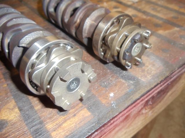
Here are a few pictures. 1st one is of the shifter segments in a 1988 motor that is being reassembled. This is right rear side. Clutch pack would go on the shaft sticking out. This is the new style segment in block. Second picture shows difference between new and old style segments, old is on the right. The small pins can come out, not allowing shift mechanism to be able to rotate cam. Last picture shows what it looks like with clutch pack in block. Gary

-
Rotors are interchangeable between 1st gen Ventures and 1st gen vmaxs as far as bolt patterns between wheels & rotors.. There are some minor thickness differences, due mainly to venting design changes. Front to rear will even interchange, I have a VMax wheel on rear with a rotor from front of MKII Venture on it. MKII rear rotor is somewhat unique due to it's offset design & diameter. Gary
-
They will not work correctly with the stock MKI rotors. The MKI rotors are 298mm, The VMax's uses a 282mm front rotor in 85-92. 1993 was when VMax went to 298 front rotors. Gary
-
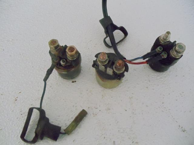
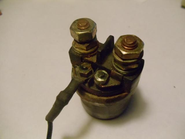
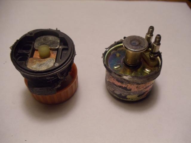
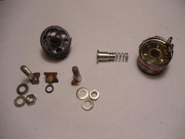
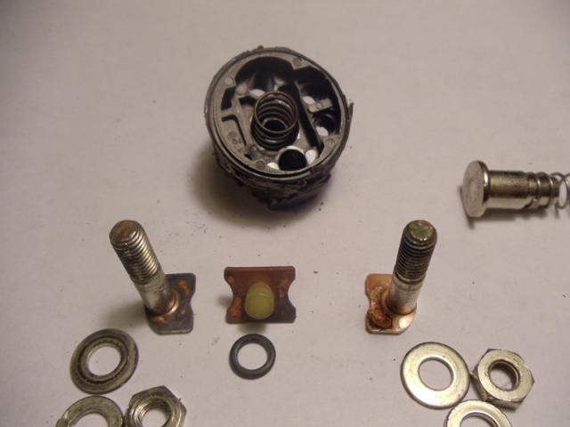
I will start this post by saying, 'No Venture parts were harmed in the making of this post, however there was an unfortunate VMax casualty' Pictures attached are of a group of solenoids from a MKI, MKII Venture and VMax. 1st picture is of on left an MKII Venture, middle is I believe an 83 Venture (probably similar to 84-85), and on the right is a VMax solenoid. [ATTACH]61706[/ATTACH] Next is shown why the MKII's only need 1 wire in control circuit, on the right side there is a jumper from the coil terminal to the large terminal that is connected to the positive battery. The MKI's and the VMax's have two wires in the small coil control circuit. The MKII circuitry is all done on the 12V- side. [ATTACH]61707[/ATTACH] This picture shows the VMax solenoid split in half. Right right side is the coil, plunger & spring. The two small studs are for the control circuit wires. Left side is the main contact set. The two silver colored pads are the tops of the studs the main heavy starter circuit wires are attached to. Between the two silver studs is a plastic plunger nub for the copper contact plate between the two studs. This plastic nub keeps the coil plunger from contacting the two stud tops when the coil is de-energized. Normally the spring in the coil side keeps the plunger in a position to press down on the plastic nub and break the connection between the two studs. [ATTACH]61708[/ATTACH] This picture shows the plunger and spring removed from the coil pack on the right side. On the left side is the two studs removed and the copper contact plate that completes the circuit. Notice the dislocation from arcing on the stud base to the left. This carbon build up is enough to cause failure of this solenoid. Not obvious in the picture is a spring in the contact black housing in the center hole. This spring pushes the copper contact plate into two stud bases when the coil is energized. [ATTACH]61709[/ATTACH] This picture shows a closer view of the contact side. Arcing damage to stud faces is more visible. [ATTACH]61710[/ATTACH] Gary
-
I will start this post by saying, 'No Venture parts were harmed in the making of this post, however there was an unfortunate VMax casualty' Pictures attached are of a group of solenoids from a MKI, MKII Venture and VMax. 1st picture is of on left an MKII Venture, middle is I believe an 83 Venture (probably similar to 84-85), and on the right is a VMax solenoid. Next is shown why the MKII's only need 1 wire in control circuit, on the right side there is a jumper from the coil terminal to the large terminal that is connected to the positive battery. The MKI's and the VMax's have two wires in the small coil control circuit. The MKII circuitry is all done on the 12V- side. This picture shows the VMax solenoid split in half. Right right side is the coil, plunger & spring. The two small studs are for the control circuit wires. Left side is the main contact set. The two silver colored pads are the tops of the studs the main heavy starter circuit wires are attached to. Between the two silver studs is a plastic plunger nub for the copper contact plate between the two studs. This plastic nub keeps the coil plunger from contacting the two stud tops when the coil is de-energized. Normally the spring in the coil side keeps the plunger in a position to press down on the plastic nub and break the connection between the two studs. This picture shows the plunger and spring removed from the coil pack on the right side. On the left side is the two studs removed and the copper contact plate that completes the circuit. Notice the dislocation from arcing on the stud base to the left. This carbon build up is enough to cause failure of this solenoid. Not obvious in the picture is a spring in the contact black housing in the center hole. This spring pushes the copper contact plate into two stud bases when the coil is energized. This picture shows a closer view of the contact side. Arcing damage to stud faces is more visible. Gary
-
Starting Problems
dingy replied to uthpda's topic in Venture and Venture Royale Tech Talk ('83 - '93)
I will start this post by saying, 'No Venture parts were harmed in the making of this post, however there was an unfortunate VMax casualty' Pictures attached are of a group of solenoids from a MKI, MKII Venture and VMax. 1st picture is of on left an MKII Venture, middle is I believe an 83 Venture (probably similar to 84-85), and on the right is a VMax solenoid. [ATTACH]61699[/ATTACH] Next is shown why the MKII's only need 1 wire in control circuit, on the right side there is a jumper from the coil terminal to the large terminal that is connected to the positive battery. The MKI's and the VMax's have two wires in the small coil control circuit. The MKII circuitry is all done on the 12V- side. [ATTACH]61700[/ATTACH] This picture shows the VMax solenoid split in half. Right right side is the coil, plunger & spring. The two small studs are for the control circuit wires. Left side is the main contact set. The two silver colored pads are the tops of the studs the main heavy starter circuit wires are attached to. Between the two silver studs is a plastic plunger nub for the copper contact plate between the two studs. This plastic nub keeps the coil plunger from contacting the two stud tops when the coil is de-energized. Normally the spring in the coil side keeps the plunger in a position to press down on the plastic nub and break the connection between the two studs. [ATTACH]61701[/ATTACH] This picture shows the plunger and spring removed from the coil pack on the right side. On the left side is the two studs removed and the copper contact plate that completes the circuit. Notice the dislocation from arcing on the stud base to the left. This carbon build up is enough to cause failure of this solenoid. Not obvious in the picture is a spring in the contact black housing in the center hole. This spring pushes the copper contact plate into two stud bases when the coil is energized. [ATTACH]61702[/ATTACH] This picture shows a closer view of the contact side. Arcing damage to stud faces is more visible. [ATTACH]61703[/ATTACH] Gary -
Starting Problems
dingy replied to uthpda's topic in Venture and Venture Royale Tech Talk ('83 - '93)
Here is a copy of the 83, 84-85 & 86-93 starting circuits for what it's worth. Gary -
Called the Jason Mod. http://www.venturerider.org/forum/showthread.php?t=501 Makes idling rougher & no real gain. The length of the vacuum hoses is about the same as the piston stroke, so there is only the same air being pushed back & forth in a 5/32" hose. Gary
-
Starting Problems
dingy replied to uthpda's topic in Venture and Venture Royale Tech Talk ('83 - '93)
Solenoid could be passing voltage through the coil and still be bad. Probably the main contact/s in the solenoid would go before coil. It could even be clicking and be toast, there is a lot of current going through that contact. Gary -
Starting Problems
dingy replied to uthpda's topic in Venture and Venture Royale Tech Talk ('83 - '93)
Starter solenoid circuit on the 1st gens has 12V+ applied to one wire when key is ON and kill switch is in Run position. The 12V- side is switched through the starter safety circuits. Put a ground from battery to the L/W wire with key on and Kill switch in run position. WITH THE TRANNY IN NEUTRAL, this will bypass safety circuits and bike will crank in gear. If solenoid does not click, it's toast. If it does click and no crank, it could still be toast. If motor cranks when you jump two heavy solenoid wires, time for a replacement solenoid. Hope I didn't repeat previous info, didn't read all the posts. Gary