SaltyDog
-
Posts
123 -
Joined
-
Last visited
Content Type
Profiles
Forums
Gallery
Events
Store
Everything posted by SaltyDog
-
 I've attached a few circuit and components diagrams from the XVZ13 manual showing the cruise control system. Check out the wire colors and see if they are the same. The 1200 and 1300 share many components so these should be close. Hope this is on some use..
 -
Have you tried the first gen tech section and downloaded the manuals there? [ame=http://www.venturerider.org/forum/showthread.php?t=3384]First Gen Service Manuals - VentureRider.Org[/ame]. Lots of good info to get you moving in the right direction.
-
Special Washer---crank
SaltyDog replied to jasonm.'s topic in Venture and Venture Royale Tech Talk ('83 - '93)
I'm getting ready to install the cooling kit on my '83 and I scanned the instructions so you can see the order and orientation of the baffle plates. The lip faces into the engine towards the stator. -
I'm in need of some parts for floorboards for a 1st Generation
SaltyDog replied to Marvin81's topic in Watering Hole
I got a answer from a seller on Ebay with the length of the spacers from his set of floorboards. He measured them and got back to me with a length of .700" for two of them and 1.0" for the other two. Not quite what we have found with my spacers and other that were measured. But probably close enough to work just fine. Their purpose isn't really critical, just needs to be enough to get the controls to clear the bike frame and are sturdy enough to support the riders weight. I got a measurement of .875", .700" and 1.0" for the three spacers I could find. So If anyone still wants to make them up for the people that need them, I have three examples that can be used for templates. I will ship them to whoever is willing to take this on. I think they could be made with the length of 2 @ 1.0", 1 @ .700" and 1 @ .875". These measurements would most closely match the lengths we have found from other members on this site. I still owe Tomphil a complete set of them so he can install a set of floorboards that he just purchased from me. I can send them on after we get the replacements made up. -
I'm in need of some parts for floorboards for a 1st Generation
SaltyDog replied to Marvin81's topic in Watering Hole
I too have a set of floorboards in need of the mounting spacers. But. I do have three of the needed four. I have one 22.30mm (~.875") long, one 17.8mm (~.700") long and one 25.4mm (~1.00") long. I have been looking through all my spare bolts and left over parts and I can't find the missing forth spacer. I can send them to be copied if we can come up with the last missing spacer length. All I want is a forth spacer to complete my set. -
I live only 90 miles west of there so I can't miss this one.
-
I have a older 4th generation Ipod and I installed a newer upgraded hardrive a couple of years ago. It is one of the things I really like about the Ipods, the availablity of repair/replacement parts. All the circuit boards, battery and display can be replaced if necessary. The hard drive (Hitachi) I found was advertised as a improved design released by Hitachi to address just this situation of vibration. It was easy to replace and hasn't given me any problem in over three years of riding in my pocket, tankbag and right fairing pocket of my bikes. I use this Ipod when I ride any of my 4 motorcyles, on the highway or off-road.
-
I recently received a PM from another member wanting to know how I remotely controlled my Ipod while riding. He was interested in some pictures and information on the solution I used and if it could be operated with glove. Below are a couple of pictures of the solution I have used for a couple of years without any complaints. I use a Griffin AirClick with my 4th generation 40Gb Ipod with the unit set on shuffle. I can operate the remote with my riding gloves to control the volume and play/pause the music when stopping. The buttons are alittle small for winter gloves though... I strapped the remote unit on the clutch reservoir to make it handy while riding. I put the Ipod in my fairing glove box and have it connected to a 12v plug to provide continuous power. I also ran a headphone extender out of the fairing to plug in my EarFuze earphones (great fitting units!). With this setup, I can keep the Ipod out of sight and the effects of weather.
-
updated Regulator/Rectifier Group Buy
SaltyDog replied to Squeeze's topic in Venture and Venture Royale Tech Talk ('83 - '93)
If you want, you can purchase the connector bodies (both types) and the crimp-on terminal with seals at www.easternbeaver.com. When I did my Shindengen conversion, I found them there sold as a set and the owner of the site listed the the parts separately. The connectors are Furakawa brand part no. (3 Position 3P250WPK-FEQLW-BK-F-300) and they are on this page http://easternbeaver.com/Main/Elec__Products/Connectors/Sealed/FKWH/fkwh.html. Just scroll down and you will see the connectors listed in a kit and the individual components. They aren't really cheap, but you get all the parts needed. NO connection with easternbeaver, just a satisfied customer. Good luck. -
I did measure the voltage at the battery with the original stock regulator and that was another reason to look for a newer replacement. My old original R/R had my old wet cell battery at around 13-13.5 volts (not bad), but then I changed over to a larger capacity AGM battery. I wanted to get the charging up to at least 14-14.5 volts to keep the new battery at it's full capacity. The Shindengen R/R will do this and since I found a brand new unit for oly $30.00 with the connectors it was a no brainer to upgrade. I mounted the new regulator under the seat on my '83 at first also but I got concerned with the low air flow and all the heat that comes off the engine. After looking around the bike I figure the airducts in the fairing offered the best location (for me) to get protection and provide cooling airflow that is not heated by the eingine while riding in the hot summer weather. The performance info for the Shindengen R/R shows the unit has to be derated for output with the higher ambient termperatures of it's mounting location. Since I want to get the most out of my charging system, I figured that alittle more cooler air would pay off in the long run. The other posts I read while researching the swap strongly reccommended to bypass the old wiring on the bike So I ran the red and black output wires directly to the battery to reduce the electrical resistance (voltage drop and heating) and posible problems. Since I already use the left and right hidden areas of the fairing (between the inner and outer walls) to mount all my new gadgets, mounting the R/R was easy. I have the R/R in the left air duct. I mounted the cooling fan timer and relays for the driving lights and dual horns in the new hidden space I created in the left fairing. In the right fairing, I mounted a bike security alarm and another relay that supplies power to the ignition and takes the load off the ignition switch and kill switch. This relay insures full voltage and current is available to the TCI and ignition coils. The ignition switch and kill switch circuits only have to provide a small amount of current to energize the relay. The new relay will carry the load current directly through a fused supply from the battery. I wanted to get rid of the accumulated voltage drop that occurs with all the original electrical components in the stock electrical path. I modified my left side of the fairing where the radio mounts and constructed an additional storage box and used a left console cover to make it look similar to the right side. The whole fairing looks stock from the outside to the casual observer. The new storage space is really handy and is big enough to hold the owners manual and my Ipod. I also added a 12v cigarrete plug in the bottom of the new box to power my Ipod. I put an extension headphone cable out through the fairing to the left sidecover so I can plug in my earphones easily while seated. With the Ipod remote control on my left handlebar the music is easily managed while on the road. I have a older 40 Gb Ipod with about 22 days of music and I am never bored with the music selection!
-
I just installed (last week) a FH012AA regulator/rectifier on my '83 std. I too was concerned with the extra brown wire in the wiring schematics. When I got down to installing the unit I found that the brown wire didn't pass through the old R/R plug. It stopped on the bike side. I ran the red wire (30 amp inline fuse) and the black ground wire direct to the battery. The Shindengen R/R runs at air temperature and doesn't heat up like the old SCR based Regulator. The FET's in the Shendengen regulator have less resistance and don't generate heat while operating. The Shindengen regulator is rated for 50 amps so it has really has alot of extra capacity. I mounted the new regulator in the left airduct in the fairing to provide cooling if it needed it and to get it away from the engine heat. I got a set of the connecting plugs from the seller on Ebay, but I found that Eastern Beaver. com has them in stock. Below are a few views of the regulator and the mounting location in the fairing air duct. I changed my regulator because I was concerned with the age of the unit and I wanted to try a newer technology regulator to try and reduce the heat problems and to move the regulator to a more protected location.
-
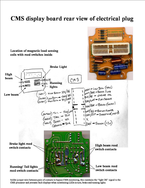
Here are a couple of views (front and back) of the CMS board with the load coils and reed switched inside them. I also have a hand written layout of the CMS plug showing the pin functions of the wires going into and out of the CMS assembly. I added jumper wires to the back of the board and bypassed the reed switches so the lighting current through the load coils have no effect on the warning display. Since the LED lights are virtually a lifetime proposition, I don't really need to monitor the health of the lighting circuits. I will bypass my headlights (high and low) at a later date when I go the HID route with the headlight.
-
You can add jumpers to the CMS board and bypass the reed switches in the load coils for the warning display. It is probably a good idea to resolder the plug connections to the board to prevent future problems anyway. I posted a picture showing the layout of the CMS boards before with the directions when I went all LED on my '83 Standard Venture. You can read the post here [ame=http://www.venturerider.org/forum/showthread.php?t=33285]Pinout of the "information display" on the dash - VentureRider.Org[/ame]. I have more pictures of the board if you need them. NOT for the faint hearted, but not that difficult.

-
I emailed the HUBB and asked about the availability of WIFI since I plan to camp while at the rally. I got the reply that it is available, so no problems. When I was up at the HUBB a couple of weeks ago, I used my WIFI finder to check the signal strength outside in the camping areas and the signal strength was pretty good.
-
think its the starter?? please help
SaltyDog replied to drizz's topic in Venture and Venture Royale Tech Talk ('83 - '93)
I had the same symptoms a couple of weeks ago on my '83 venture. I had been riding the bike and when I stopped for fuel and tried to start the bike it turned over very slowly and then wouldn't do anything but click the starter solenoid. I had a fully charged battery, large automobile size cables and I had rebuilt the starter last year (about 4 thousand miles ago) with new brushes, bearings and additional ground wires. I too suspected the battery (wet cell only 1 year old) and had a friend bring some jumper cables, no change. I then connected directly to the starter and still it wouldn't turn over. My bike would also draw down the lights (dim) when trying to start it with the key. The starter was pulling alot of power, but not turning the engine over. I then pushed the bike and let out the clutch to make sure the engine wasn't locked up. All this happeded in a gas station parking lot. When all else had failed I got my trailer and dragged the bike home to my shop. Knowing that the only thing left was the starter being bad, I tore it apart and found one of the motor brushes had worn down and was barely touching the commutator. I put in a older good set of brushes and reassembled the starter. I was very happy to see that the starter cranked the engine perfectly after the brush replacement. The rebuild kit I used must have had a defective (soft) set of brushes. I went down to my local starter rebuild shop with one of the old brushes and got a pair that matched the Venture's so I will have a spare and I will check them again after the summers riding season. Long story to get to the advice you were asking for... check and clean the starter. -
Thanks for the additional information. I did install a flasher relay without the "bulb out" feature, but I will check about the 4 vs. 2 lights. I changed the #194 bulbs in the instrument cluster to LED's first before I tackled the #1156 and #1157 bulbs and the CMS fault display. I agree that the daytime visibility is much improved and the extended longevity of the instrument cluster lighting is important to me. I hate having instrument lights go out at night and not being able to see the tach and speedo.
-
I too needed to find the pin assignments for the CMS on my Venture ('83 standard). I wanted to change all the running and turn signal lights to LED. Not wanting to stare at the CMS blinking continuously due to the load change, I dug out my spare instrument cluster and wiring harness. After comparing the wire colors on the harness plug and the electrical schematic, I figured which pins on the CMS fed the magnetic coils and reed switches and their functions. I added two jumpers on the back of the plug board to bypass the tail light and brake light reed switches. This way the CMS processor doesn't sense the less than design current load through the magnetic coils. With the reed switches bypassed, I can run any combination of bulbs in the brake and running/tail light circuits and not get a fault display. Since the LED bulbs have a LONG lifespan, the lack of failure warning isn't a problem to me. I also replaced the hazard and turn signal thermal relays with electronic types from my local Autozone. The hazard relay is a standard 2 pin type and was a direct replacement. To replace the turn signal relay, (3 pin type, without bulb outage), I had to move two of the connectors in the 3 pin plug to get the turn siganls to work. I swapped positions of the brown and brown/white wires in the plug and the new electronic relay worked fine. I did lose the self-cancel function but the switch on the handlebar will cancel the signal without any problems. I found when I had changed all the turn signal bulbs to LEDs that I needed to add a load resistor to each side to regain proper function, dispite the use of the electronic turn signal relay. I am still working on eliminating these load resistors if I can figure which component in the bike wiring is requiring the additional current for proper turn signal operation. I picked up some 10 ohm 25W resistors online at www.partsexpress.com. Below you will see some more explanation of the pin layout and functions. Look carefully and verify everything on your unit before you do any modifications. Everything I've discussed I have completed on my '83 Venture standard so I know it works for my bike and I hope it is of some use for someone else.
-
I recently picked up a spare Venture engine that was listed as a 1983 Yamaha Venture Royale XVZ12TDK. I am curious if this is the true year of production. The motor number is 31M-002788. Does anyone know of a online cross-reference for the Venture engine numbers to production years. The number range for each year would be really helpful. If someone has a bike with an engine that is close to mine would be useful also. I have searched this forum and others for a cross-reference and various online search engines without anything useful popping up. Thanks for any help..
-
I'm interested in a stronger fork brace for my '83 standard XVZ12.
-
Oil pressure gauge?
SaltyDog replied to timgray's topic in Venture and Venture Royale Tech Talk ('83 - '93)
I too wanted a gauge to check the oil pressure after I read about all the troubles the Vmax riders have with the bottom oil distribution piping blowing o-rings. This normally only occurs if you rev up the engine too much before it warms up. I figured that it would be a good tool at startup to verify correct oil pump operation. I had also heard that the oil pressure was to low to be usefull, but I went ahead and installed a 0-100 psi. mechanical guage. Since our engines have plain main bearings I knew that a minimum oil pressure had to be maintained to keep the metal to metal contact to a minimum. I tied the oil pressure sensing line to the gallery plug below the waterpump housing. When I start up the engine the oil pressure runs at almost 80 psi and drops to 25 to 30 psi when warmed up and cruising at 60 MPH (~3200 RPM). At idle it does drop to about 10 psi, but still readable. I'm happy with the results and the guage gives me the proof that the oil system is working properly. Before I installed the oil pressure guage, I removed the bottom engine cover and cleaned the oil pump pickup strainer and replaced the o-rings on all the metal oil distribution piping. -
I would be interested in one of the VentureRider patches. Thanks for all the work getting these out to the group!
-
PM sent
-
How many will buy carb diaphragms
SaltyDog replied to Freebird's topic in Venture and Venture Royale Tech Talk ('83 - '93)
I'll take one set for my '83 if it all comes together..