
Search the Community
Showing results for tags 'wire'.
-
I have just purchased a new KOSO GP Style Tachometer with Water Temperature, BA551B23, (first item on page 12 here): http://www.kosonorthamerica.com/ Paid $150, delivered. The idea was to reduce the number of gauges I need by one to fit them all under the dash, like this: [ATTACH]46369[/ATTACH] So far, my report is decidedly mixed. First, the gauge is very impressive in the details of construction and parts supplied. But that is dampened by the absolute WORST Chinenglish - no, let me rephrase that - the documentation that comes with this thing is not NEAR good enough to be even derisively called Chinenglish - let's say Chinengiliberish! Not only is the wording so bad that much of it is totally unintelligible, but a few very key points are absolutely WRONG! The wiring harness is very impressive, with each section connected by plugs. The harness for the water temp sensor is just barely long enough for our bike, but I guess that is better than being too short! The tach input can be picked up by EITHER connecting to a coil or wrapping a wire around a spark plug lead. Compared to the minimal length of the temp sensor wires, the wires for connecting to a coil are plenty long enough to connect to your buddy's machine as he rides next to you on the highway. The gauge mounting hardware is all rubber mounted, and while the bar clamp is specifically sized to use on a normal 7/8" bar, it will work on our 1" bars with a bit of effort. The gauge itself is a bit larger than the 1 7/8" mini Drag Specialties tach which I prefer, but if you get it positioned just right it does fit under the dash at full lock, but just barely! Partially because this gauge is completely electronic, the wire connections are just slightly different than usual - one wire connects to battery hot, and another wire connects to ignition 12V. There is no separate wire for dash lights, so they are on all the time. While this probably makes no difference to most folks, it irks me a bit since I have the other gauges wired separately to a switch specifically for dash lights. Oh well . . . I can learn to live with that. The tach is truly a universal tach, as there are settings to select for both two stroke and four stroke engines, from one cylinder all the way up to 12 cylinders! But you do need quite a bit of imagination to understand what the instructions are trying to tell you about how to set those selections. Likewise, the temperature gauge can be set to display either Celsius or Fahrenheit. Unfortunately, the biggest issue is that the gauge did not work for more than 5 minutes! Everything seemed fine when I first hooked it up and set the proper formats, but the next time I turned the key on, the LCD display (temperature and configuration settings) was completely blank. The tach still seems to work OK, and the lights are on, but I can't get anything from the mode buttons or any display at all on the LCD screen. So now I am waiting to see how much trouble it will be to get this thing replaced. I'll let y'all know how that comes out. Goose
-
 Hi all, just got a 83 Venture xvz12 and have some headlamp issues. Somewhere down the line someone jumped the headlamp power wire directly to the headlamp. All I have is lowbeam and the icon on the display is lit up and a flashing warning lite. I suspect the Reserve lighting unit may be bad, I have battery voltage going to it at the green/red wire if I remember correctly. Is there a way to test this unit or bypass it? What exactly does this unit do? The manual does not seem to be a wealth of info here. Any other suggestions? Any input greatly appreciated,thanks, Neil.
 -
If you test thre wire 0 ohms it is copper. In the end cap there is a resistor of some kind. can't be tested with o meter. How do you know if it is good or not.?
-
OK. I've added some red flexible LED strips to the chrome pieces behind the saddlebags on my 2nd Gen Venture to augment my brake lights, but, I can't get them to work. I know the strips work because when I connect them directly to the battery, they work. I tried wiring them to the yellow wire (brake) & a black ground wire to no avail. Can anyone help me with this? Thanks.
-
 Someone asked me how I converted my Tape Deck to a MP3 Player. The best info I have is here: http://www.venturerider.org/forum/showthread.php?t=41100 I used Scotty's and Frankd's schematics to come up with one that works between the two. Here is a simplified color diagram I created. http://i19.photobucket.com/albums/b160/warthogcrewchief/SimpliedInstructionsforMP3Input.jpg Here is where I located my 3PDT switch. http://i19.photobucket.com/albums/b160/warthogcrewchief/100_0955.jpg Here is the "tray" I made out of (aprox.) 1/4" thick clear acrylic plastic. I cut it out using a dremel and razor blades and then glued them using plastic glue. I got some simple hinges and drilled holes and screwed in screws (put plastic glue on threads). http://i19.photobucket.com/albums/b160/warthogcrewchief/100_0956.jpg I then cut off the rest of the screw that protruded through the plastic (cut slowly because it heats up fast!). After that, I placed a drop of glue over the rest of screw in hopes of it staying in place. After it's all dry and the holes are cut, I painted it with flat black paint on the inside and the blue paint to match the outside. Oh, almost forgot the magnetic latch assembly I installed as well... It was a pain to cut the plastic out and get it to fit...lots of glue to fill the voids. I also had to cut into the plastic face to make it fit. Notice the screws I used to hold it in place so that it doesn't shift. That may be required to keep it in place. Once again, cut off the excess protruding screw and cover it with either RTV or glue to prevent any scratching of items placed in there and backing out of screw. http://i19.photobucket.com/albums/b160/warthogcrewchief/100_1056.jpg I found a "marine" grade 12V outlet. In installed it and then made one wire connect to a ground on the frame. The other wire connects to the right side of my accessory fuse spade and then the left side of the accessory fuse connects to the positive battery terminal. NOTE: I'm using the fuse box made by Skydoc_17 that mounts in place of the factory fuse box. *Something not mentioned in my schematic is that the common (ground) wire inside the 3.5mm headset wire is usually unshielded wire wrapped around each (Left and Right stereo) wire. You'll have to unravel the bare wire and twist the two together to make a common ground that connects to the black wire from the bike's cassette harness. EDIT: Here is where I found the "Marine Grade" 12v Outlet at Amazon.com [ame=http://www.amazon.com/Marine-Grade-Cigarette-Lighter-Socket/dp/B0002KRC5Y/ref=sr_1_2?ie=UTF8&s=automotive&qid=1274422515&sr=8-2]Amazon.com: Marine Grade Cigarette Lighter Socket 12 VDC: Automotive@@AMEPARAM@@http://ecx.images-amazon.com/images/I/31BRN43V71L.@@AMEPARAM@@31BRN43V71L[/ame]
 -
I'm installing a Back-off brake module and was wondering where to attach the ground wire. Should I attach it to the frame or the battery? Thanks
-
Moved this thread from the Watering Hole... Profiessional Input Please: I have read most of the threads regarding wiring of a Stebel Horn. I ordered one today so it will be on for a trip I am taking the end of May to Dragon/Cherohala area. I have decided to go with the "in cowling" mounting option. After reading Freebirds Tech article and others here on the forum I would like "confirmation" that I will be wiring it up correctly. 1. Mount horn vertically in cowling to frame. (Using pipe insulation to cushion per a suggestion on a thread and tie wraps) 2. Splice into hot wire from acc. plug and run wire to relay. ( Per Freebirds Tech article) (Increase size of fuse in lower fuse panel) 3. Wire from relay to horn positive. (Tech article) 4. Ground wire from horn to frame. ?????? 5. Splice into pink wire horn button and run wire to relay. (Threads tech article) What am I missing...anything. NOTE: I restored a 110 year old house here in Lynchburg. I did all restoration work "EXCEPT" electrical....Just not my thing..... Since I am under the cowling and want to keep the OEM horns active, do I need to deal with the "brown" wire everyone refers to in the mounting option on the lower right side of the bike?.... Long Tall in Lynchburg, VA
-
 I just installed the Argus Battery Bug and it works great. 100% battery capacity and voltage reads between 13.7 and 14 while running. Drops down to 13.2 when parked. At the same time I disconnected my Signal Dynamics charging indicator to be replaced by a digital meter. Here is where im seeing differences in the charging rate and where my questions lie. As stated, the Argus is showing full charging. This gauge mounts directly to the + &- side of the battery for a direct read. The digital gauge is wired to a ground and the + lead is tapped into the ignition wire under the fairing. This is where im getting a lower reading from the digital gauge. 12.9 while running down to 12.2 fully loaded with all switches and lights on. Yet the Argus BB shows the charging volts at the battery in the 13 range. Did I do something wrong here? Why would there be such a difference in readings? Is there a better place to hook up this digital gauge other than the ignition wire? Its the pink with yellow striped wire. My driving lights are also tapped into this line. Help!!!!
 -
I am looking to hook up my heated gear.My plan was to run a relay off of a wire that is only hot when the bike is running. Does anybody know of such a wire on the RSDT? I have them on my cars and have had them on 2 Yamahas. I have studied the wiring schematic but I can't find one. Thanks
-
i've searched the tach install threads...and what i need to know is.....what is the white wire for on the rt frnt coil....and the red/black wire ,which is common for all the coils... thanks
-
Is there a fuse that is on only when the bike is running? Would like to add a relay for new HID headlight and wire the relay to come on only after the bike has started.
-
 I have a 83 VR with an 86 motor (previous owner changed motor, instead of fixing 2nd gear) and have bought a heavy duty stator and regulator/rectifier from Buckeye Perf. and installed the stator OK and works good, but then noticed that the instructions for the R/R said to cut off the brown wire in the wiring harness and discard it. The R/R is a knockoff and not a Yama part. I am wondering what the brown wire is used for and if I can cut it off without any bad effects. Can I safely cut and discard this brown wire? Electrical wiring diagrams are just gibberish to me, so they are no help. I know enough to get in trouble and electrocute myself. The Service Manager at the local bike shop said it was OK to cut it off, but he didn't sound like he knew what he was talking about. He didn't even ask what year or model bike I had. I just told him I had an older VR. The bike has been sitting in the back of my garage, since last fall, because of overheating problems, and not charging. Put the new stator in, in the fall and then lost interest because of the overheating problem. I have a GW, so there was no hurry to fix it. If I can get the R/R unit in and working, I might work on the overheating problem (long story) and if I can't, then I will part out the bike over the summer. I have owned this bike for three years, but have only ridden it sporadically because of the overheating problem and now the electrical problem. Thanks for any help. Jim
 -
Profiessional Input Please: I have read most of the threads regarding wiring of a Stebel Horn. I ordered one today so it will be on for a trip I am taking the end of May to Dragon/Cherohala area. I have decided to go with the "in cowling" mounting option. After reading Freebirds Tech article and others here on the forum I would like "confirmation" that I will be wiring it up correctly. 1. Mount horn vertically in cowling to frame. (Using pipe insulation to cushion per a suggestion on a thread and tie wraps) 2. Splice into hot wire from acc. plug and run wire to relay. ( Per Freebirds Tech article) (Increase size of fuse in lower fuse panel) 3. Wire from relay to horn positive. (Tech article) 4. Ground wire from horn to frame. ?????? 5. Splice into pink wire horn button and run wire to relay. (Threads tech article) What am I missing...anything. NOTE: I restored a 110 year old house here in Lynchburg. I did all restoration work "EXCEPT" electrical....Just not my thing..... Since I am under the cowling and want to keep the OEM horns active, do I need to deal with the "brown" wire everyone refers to in the mounting option on the lower right side of the bike?.... Long Tall in Lynchburg, VA
-
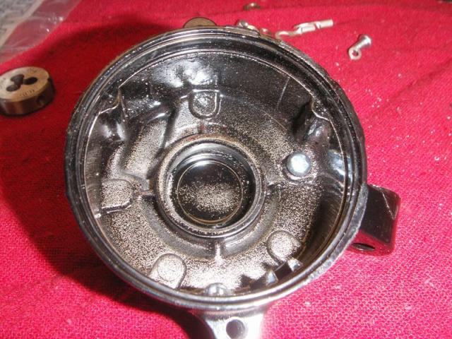
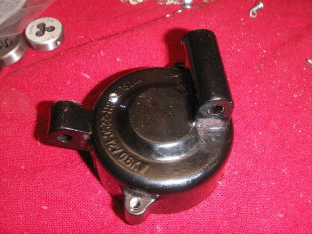
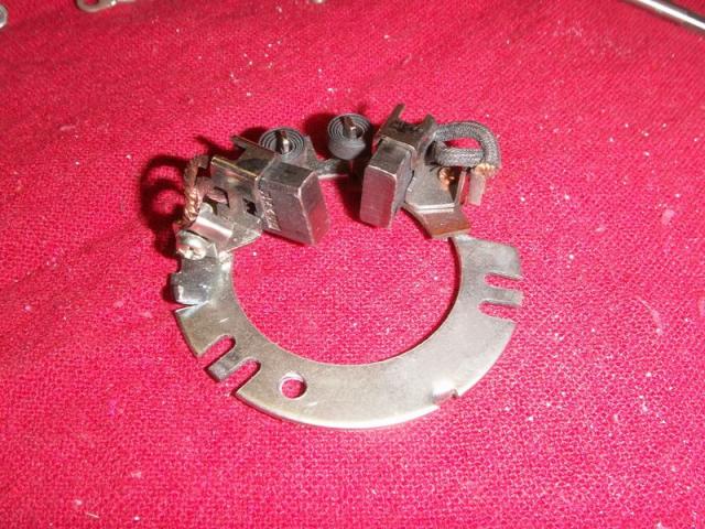
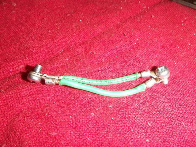
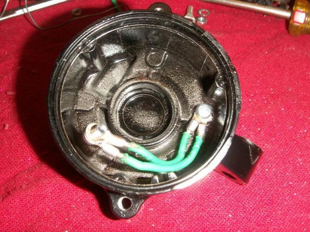
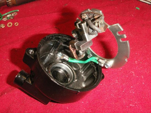
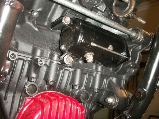
Attached are some pictures of the modification I made to the starter on my 83 1st gen. The purpose of this is to give a better path to ground for the brush plate. Stock version allows a path to ground through the tabs around the plate. Snaggletooth had posted about this mod several weeks ago, but I do not know of any pictures that are available to show it. Gary This shows the location of the drilled & tapped hole. I used a 4mm screw to attach wire with. Hole is at 2 o'clock position. This shows location of hole from outside of cover. The hole in the brush plate is shown at the 7 o'clock position. Picture of grounding wires. I used two 14 gauge wires. The terminals for 12 gauge and up had too large of a mounting lug for mounting screw size I wanted to use. Wires attached to end cover. Wires attached to brush plate. View of starter mounted on engine. I have since added an 8 gauge wire that runs from the bottom mounting bolt for the starter to the right side of the engine block. I attached wire to the block at the same point the main ground wire from the battery attaches.

-
First of all I would like to say thank you to everyone who helped last time. I now have brakes all the way around and i found a broken wire on the kickstand switch. I have now came across more problems. First of all does anyone have a CHEAP set of front rotors? Mine are both bent. I have a 1988 venture. Second problem as i put this bike back together after getting it in pieces. I have found 3 wiring plugs that I cant find a home for. The first is right behind the headlight it is a flat 3 wire plug that has a white end on it. The 3 wires are red and blue, red and either yellow or light brown and then black. The second plug is green in color two plugs one sits sideways on top of the other. The wires are light brown and black. The third plug is sticking out where the harness turns down from top to go to kickstand. About front of seat. It is a 2 plug black on end and has protective cover over the two wires. One wire is red the other is black. I know they have wiring diagrams on this sire however they show everything. The radio, CB, and everything else. My bike only has cruse nothing else. Since i didn't take it radio apart i don't know if there was even anything there. If anyone could help I would really be grateful. I dont know if it is part of it but on my dash the battery light is showing. I am guessing it is not charging.
-
my friends car is fixed, was able to know which wire was for cam sensor from your picture, made sure wire was connected good, disconnected battery reconnected it and no more check engine light, 2 days now,thanks again
-
 I was replacing the spark plugs on my 97 Tour Classic and in the process of struggling with removing one of the spark plug wires the wire came out of the boot. Seemed to be much too clean of a break; looked like it was cut with a knife the break was so clean. How do these connect within the boot themselves? I am assuming I now have to replace the entire assembly (coil plus wire), correct? Is there any way to repair it?
 -
I know this has been covered many times before. I have a 2000 RSV that I want to wire for my trailer. I have a modulite that I tried to hook up per Freebirds article, but never got it to work. Got it off Ebay a good while back. Might be one of the bad one's that I hear about. The trailer is 100% LED. Do I have to run a modulite? Or, can I wire into the wiring behind the license plate. The trailer is a flat 4 wire LED kit I got from Harbor Freight. If I can tie directly into the wiring behind the license, will I be able to wire in a round 5 wire coming from the bike, and use a round adapter(pictured in attachment) that changes to a flat 4 wire to connect to the trailer? I already have the adapter and have hooked it to my pickup and the trailer works perfect. Brake lights, turn lights, etc. It is a six wire adapter to a 4 wire, looks like it will work on a 5 wire round hookup also. Thanks in advance for any help. Charles
-
There's a few of you who have read/replied to my thread regarding my '89 backfiring a lot.http://www.venturerider.org/forum/showthread.php?t=45485 I posted a little bit about the no spark condition on the right rear cylinder. I tested the coils, and are within limits, all three other spark plugs work just fine. I tested the spark plug wire installed on the coil and the plug cap removed - got good resistance. I then tested the wire with the cap on and the cap by itself and was having a hard time getting a good resistance value. I had to turn the multimeter onto 200K ohms to get a reading. I'm thinking that the spark plug cap may be the problem. Anyone have other ideas? I've got new wires/caps on order. Hopefully that'll fix the the problem! Has anyone had a no-spark condition before from the spark plug cap or the spark plug wires?
-
way watching,tv last nite,question was ask what was the first thing that you remembered,as a child,two things for me 1.my brother going off to wwII [1944] 2.running into a barbed wire gate other things,not sure weather,i was told about or not lowell
-
I need some advice from an electrical guru. I am trying to put passing lights on my 2001 RSV. I want to use a relay however the passing lights are for a Road Star. In the alternate wiring diagram the power goes from the positive side of the battery through a fuse to #30 on the relay. From there the power goes from #87 to the positive side of the passing lights. #85 on the relay goes to ground and #86 goes through a switch and is connected to one of the 3 wires going to the headlight. Red with a yellow strip if I want the passing lights on all the time (as I do). My headlight does not have a red with a yellow strip wire. Problem #2. My passing lights have a switch built into the left passing light and the power (positive) goes through the switch. The right passing light has a red wire with a yellow strip. The left passing light has a red wire with a yellow strip and a plain red wire. I have connected the red wires with a yellow strip together with a wire running between the two lights. The left passing light has the red wire and the red wire with a yellow strip both connected to the switch. I have connected the red wire to another red wire that will go to the relay. The alternate wiring diagram shows the switch on the negative side. Is there anyway to connect the relay show that the switch is on the positive side. Any and all help would be greatly appreciated. Thanks, Harry
-
My bike was wired for a trailer already when I got it. It has a converter under the seat and a four wire pig tail for the trailer hook up. The trailer that I just picked up is an Cycle Mate brand. It has two brake / running lights and two amber turn lights hanging off the back. The trailer is wired with a five wire hook up. And now we get to H E L P. Can I re-wire the trailer to still use the red brake / running and amber turns, or am I going to have to replace the light assemblies with combo brake / turn / running units? Thanks for the help, I have zero experience with five wire trailers.
-
 I have a couple projects for my '06 RSTD where I have been told that I ought to wire the device straight to the battery, or words to that effect. The idea is to not tap into an existing wire, but to get closer to the original source of power. Air horns, where they need lots of juice to get really loud. My passing lamps, where I want to have them on regardless whether the headlight is on high or low beam. I'll wire a relay so that if the running lights are on, the passing lamps are on. My question is: how? How do I energize these? What is the physical connection, and where? Do you go into the fuse box, or splice a wire, or what? For the passing lamps and other front-end projects, how do you get the wire back to the battery? Do you remove the tank and find some sort of cable chase to run the wires? I suppose duct tape ain't the thing. I've delayed re-doing my passing lamps because of my lack of understanding, and I am buying myself a pair of Bad Boy air horns from Harbor Freight for Christmas. So I am hoping to spend between now and then understanding what to do and maybe doing the passing lamps. I'm not a dunce, but photos would be invaluable. But really, any help would be very appreciated. Dave
 -
I just bought a 1984 VR and like a dummy i hooked the battery from my car to it with jumper cables i did not start the car but it did start and run my problem is a wire connction started melting it is a three wire conctor that gose under the motor the wires are all the same color and the concetor has came apart plz help this dummy bart:crying:
-
Can one of you smart folks out there tell what these are? Left rear cylinder has a chromed wire loop and a small curved chrome plate on top. Right rear cylinder has a chromed wire loop on top. I'm baffled! Thanks to anyone who solves my mystery.


.thumb.JPG.2b1dc631eccfc19293a750f948a0b833.JPG)


