dingy
-
Posts
5,403 -
Joined
-
Last visited
Content Type
Profiles
Forums
Gallery
Events
Store
Everything posted by dingy
-

Venture Royale rear brakes
dingy replied to thetoyho's topic in Venture and Venture Royale Tech Talk ('83 - '93)
[ame=http://www.venturerider.org/forum/showthread.php?t=21537]Reverse bleeding? - VentureRider.Org[/ame] http://www.venturerider.org/forum/showthread.php?t=15245 Look at threads above for bleeding ideas. Also remember the anti dive valve on front end. Bleeding the rear brake on these bikes will will give you gray hair. I could be wrong on this next one, but I don't think an 85 had the bleeder by the top of the fork. I think this started with the 86 model. Gary -
Any way a moderator can combine these two threads. Thank You
-
Wind chill has no effect on inanimate objects. If the air tempreture is 34 Deg F and you set a glass of warm water in this air, it will not freeze. If you start blowing air across this glass of water it will still not freeze. Temperature is still 34 deg. However the presence of this moving air will serve to accelerate rate at which the water temp drops to the air temp. In reality, air moving across inanimate objects tends to raise their temperature due to the friction that is being generated. Effect is negligible at low speeds, but consider the space shuttle re-entering the atmosphere, very cold at those altitudes, but exterior of shuttle gets very hot due to speed of atmosphere moving past it. It doesn't matter that shuttle is moving and not the air, effect is the same.
-
I think I-40 is just a tad north of Phoenix. About 70 miles or so
-
Hope this is PG rated, partial nudity http://i1007.photobucket.com/albums/af193/gdingy101/turkey.jpg
-
You ain't rite boy. Better stick to the matches idea.
-
PM me your email & I will send it to you. I can either send in PDF or MS Word 2003 format. Gary
-
Just out of curiosity, why does a chrome oil filter cost less than a black one? EMGO 10-82220 You have some good prices on parts. How about listing valve cover gaskets, I'll be needing a set of those as well as all side covers and oil sump gaskets. Gary
-
Having taken a look at the complete schematic I posted for the RSV's (one with all of the wire connectors on it) [ame=http://www.venturerider.org/forum/showthread.php?t=42357]2nd Gen Wiring Schematics 99-09 RSV[/ame] I still think this will work, but the point in the circuit to insert it is 'Fuzzy" A schematic is a representation of the circuits. It is not however a point to point wiring diagram. The connections in the wiring harness may not be exactly as shown on the schematic. What I am trying to say is that I may show a wire connection near the headlight for example, on wire 'XYZ' when in actuality that connection in the wiring harness is by the fuse block, still on wire 'XYZ'. Another way of looking at this is assume a wire going from point A to point B. This is easy, one way. Now add a point C. Does the wire for point C come from point A, or point B, or in between the two points. The more points in a circuit loop, the number of potential paths is increased. This means that there could be circuit loops inside the wiring harness that I am unaware of. An example is the ground loop I show. I know this is not actually what is in the wiring harness. Electrically it is correct though. (I hope !!) Attached is a portion of the 'Full' schematic from the upper left corner. I have noted point to insert circuit shown on previous post. Only way to be sure this is right is to trace the Br wires coming out of the Flasher and Hazard relays and find where they are connected. This may be as easy as one or the other having two Br wires coming out of the connector that is on them or it may be inside the taped portion of the wiring harness. Again, not having a RSV makes this difficult for me to pin down. Gary
-
What Buz said is correct. In the first sentence of the write up I did I said " Basically, a relay is an electrically operated, remotely controlled switch" The single pole relays that are described in that write up do not allow much in the way of complex circuitry. I have worked with relays in the past that had eight sets of contacts operated by a single coil circuit. With this size relay, the possibilities are greatly expanded . Take a look at the RSV Flasher Modification post above. The use of a Single Pole Double Throw relay inserted into the existing wiring allows the basic function of bike to remain the same. The 4 ways still work when the hazard button is pressed as before. But with this modification, and with no other switches being added, the operation of the circuit is changed. Now the circuit can work with the key off, and it overcomes the problem Ponch was having by causing the lights to come on. For the most part, anything that can be accomplished with a Single pole relay can be accomplished with a standard On/off switch with sufficient current capacities. A relay allows electrical control of these circuits without other user intervention. Gary
-
What appears to happen when you put positive battery on the Br wire feeding the hazard relay, is that energy back feeds through the signal fuse and in turn energizes the all of the fuses tied to the Br/L wire coming out of the key switch. I don't have an RSV available to try something out. Look at the circuit in the attached PDF file. The relay to the far left is added. The Br wire is cut where I noted. This circuit will energize the relay whenever the hazard button is closed and feed energy to only the flasher system. This will work with the key off. The tap into the R wire that I showed by the Rectifier /Regulator could be done at any point along the R wire circuit. It would possibly be easy to do at the Condenser leg of this circuit. The wire to the condenser is probably lighter gauge than the main R wire, thus easier to solder to. I do not know the circuitry inside of the hazard or flasher relays themselves. Gary
-
I have made a write up covering some basics on the use and installation of relays in motorcycles. I worked in railroad signaling for 15 years and most of this time I was a signal circuit design engineer. I primarily dealt with relay based design involving signaling and highway crossing protection. During this time, I gained some knowledge concerning relays and the design of relay based circuits. The write up refers primarily with the relays used in Ventures. It does not include any information regarding the starting solenoid or flasher relays. I have included some basic information and definitions regarding relays. There are pictures of the internal workings of Venture and automotive style accessory relays that are available at various auto parts stores. Also included is some basic information involved in wiring and fuse size selection. I have included examples of several practical applications of relays involving Ventures including: Driving lamp addition Passing Lamp addition for RSV’s Headlight cut-out when starting for RSV’s Air horn addition Ignition switch bypass modification for RSV’s To open the PDF file, click on file name shown in blue below. Relays 101.pdf
-
Irregardless of the discrepancies in the initial reporting or the wishes of the second civilian officer involved, this woman was brave enough to run towards hostile weapons fire. Her actions at Fort Hood should not be tarnished. Is it possible that while this woman was engaging the shooter and being shot multiple times, that the second officer was able to approach the gunman while he was reloading and incapacitate him. Below is a link detailing accounts of second officers involvement. This was published 11/12/2009 http://www.texastakeover.com/world-news/6536-second-officer-gives-account-shooting-ft-hood.html Gary
-
Current draw of brake circuit
dingy replied to Grisolm1's topic in Venture and Venture Royale Tech Talk ('83 - '93)
Bill, Here is a link to the simplified wiring diagram for your bike. Look at the right side some what center. You will see the EAND relay. If you unhook the valves there should be no path for voltage out of this relay. Another option is to locate the EAND relay and pull it out of the socket. That should totally disconnect the anti dive valves. You would be able to locate this relay by repeatedly pressing front brake lever with key on and determining by feeling which relay is actuating. http://www.venturerider.org/wiring/86-89%20Yamaha%20Venture%20Simplified%20Circuit%20Diagram%20Rev%20D.pdf Gary -
fuses / headlight
dingy replied to barend's topic in Venture and Venture Royale Tech Talk ('83 - '93)
Attached is the simplified wiring diagram for the 83. Same as what I have and it is different from the 84-85 models in many places. The headlight circuit goes in and out of the CPU unit. Also the reserve lighting is tied in. The #10 Tan wire is probably the Br wire coming out of the main switch. I know of no fuse that would affect the high beam and not the low beam in a stock wiring setup. There is a write up at link below for working on CPU unit. [ame=http://www.venturerider.org/forum/showthread.php?t=33328]Information Display Repair - VentureRider.Org[/ame] I had a similar problem with my 83 two years ago. My solution was to remove the CPU and reserve lighting unit from the headlight circuitry. This left me with the red warning light flashing (which I blacked out) and the headlight icon lit on CPU. Gary -
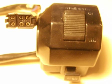
I have made the following write up of the process of cleaning the throttle side switch housing that came off of a 1983 Venture. This switch is from a Venture without cruise control. The 1983 to 1985 models should be similar. The pictures show the switch completely removed from the bike. I would recommend removing switch from bike if you perform this cleaning. There are a number of small springs and ball detents that are very easy to lose unless you have a large well lit working area. If you are unable to open the PDF file, PM me with your email address and I will send it to you. I have detailed the clutch side switch in another thread. Picture below is of the switch detailed in this PDF file. 38774.pdf

-
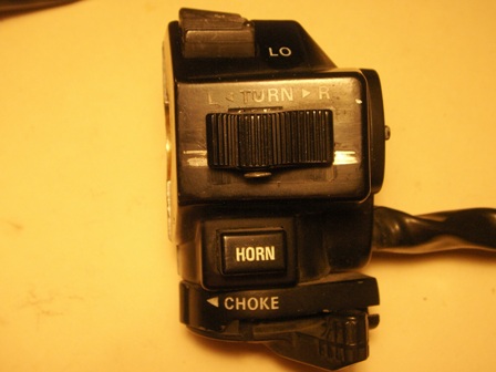
I have made the following write up of the process of cleaning the clutch side switch housing that came off of a 1983 Venture. The pictures show the switch completely removed from the bike. It is fairly lengthy, 37 pictures, but thorough. I would recommend removing switch from bike if you perform this cleaning. There are a number of small springs and ball detents that are very easy to lose unless you have a large well lit working area. If you are unable to open the PDF file, PM me with your email address and I will send it to you. I have detailed the throttle side switch in another thread. Picture below is of the switch detailed in this PDF file. This is the style of switch that the turn signal button is pressed downward to cancel. 38772.pdf
-
I have made the following write up of the process of cleaning the front and rear brake switches and the clutch switch that came off of a 1983 Venture. The switches should be the same for the 1983-1985 models. The switches detailed are from a Venture without cruise control, switches from cruise control equipped bikes are different. Cruise control equipped switches will be similar to the 1986-1993 switches shown in another post. The pictures show the switches completely removed from the bike. If you are unable to open the PDF file, PM me with your email address and I will send it to you. I have detailed the throttle side switch and the Clutch side switch in other threads. 38771.pdf
-
Something else that I just thought of: I am sort of old school, went to Industrial Electronics Tech school in early 70's and worked mostly with analog meters (type with a needle and scale). I use mostly a Simpon 260 VOM, I have a Beckman digital but I prefer the analog. I don't know if this testing will work with a digital ohm meter. Some of the more tech type guys here may need to chime in on this. Gary
-
What you will see when you hook an ohm meter up to a functioning capacitor is an in initial low resistance reading that then tapers off to infinite. This is due to the initial rush of current into the cap, then as it charges the current flow subsides. It is this high initial current flow that causes the meter to show low resistance. Prior to testing a capacitor like this I would recommend shorting the two leads together to discharge any stored charge in the cap. This is to prevent ohm meter damage. For an open cap you would see a high reading that does not change. With an shorted cap you will see a zero or low reading that does not drop. Use the highest ohms scale on meter and drop to lower scale levels repeating test.
-
I don't believe that you can check a capacitor with an ohm meter accurately. The reason being that an ohm meter has a bettery in its circuitry to provide current flow to resistors being checked. It is the amount of this current flow that is used by the ohm meter bridge circuits to calculate the resistance value. The problem with checking a capacitor is the battery in the ohm meter starts charging the capacitor, thus giving a misleading current flow reading. A capacitor definition is an electrical device characterized by its capacity to store an electric charge. The ohm meter is providing a source of electrical energy to charge this capacitor. In theory a capacitor should have an infinite ohms reading, as in an open circuit. The capacitor internals are two metallic surfaces separated by an insulator. Gary
-
Rosebud, I stopped by the local recruiting station this morning and talked to the Marine recruiter. He said that he would try to get a copy of this for you. He said that they do get copies of this magazine. Also stopped at Amvets post and talked to post commander. He seemed confident he could locate a copy. He was going to put a call out to the other local posts such as VFW and try to get one. I will let you know if either of these people come through. Gary
-
little green connector??
dingy replied to warthogcrewchief's topic in Venture and Venture Royale Tech Talk ('83 - '93)
The good news is; 59J-88188-00-00 (this appears to be official Yamaha P/N, this is same # as in parts fiche.) This is the part # from Babbits Sport Center It is on the Audio 1 page Item # 81, Filter, Noise This is from Bike Bandit 294446-001 Same page as Babbits The bad news is; $70.00 & they both show as unavailable. There might be one available on ebay now. Do a search on this item # 150379439388 The item at the top of picture appears to be one. I have never seen one of these so this is a guess. Maybe one of the owners of these bikes can verify this. He wants $69.00 for all the relays or best offer. One other thing to keep in mind, there are two items on the bike referred to as 'Noise Filter'. One is in the power supply feeding the radio, and this is the other. They are not interchangeable. The second one is item # 52 in Babbits & Bike Bandits listings. I also looked at the original schematic in the service manual for this bike. There they call it a condenser, in the parts fiche they call it a Filter, noise. I am fairly sure these two are one and the same. Gary -
Rosebud, This is from the Marine Corps Assc. web site pertaining to ordering back issues. I am not a member, or I would gladly help. https://www.mca-marines.org Are back issues available? How do I order them? Yes, back issues are available. If you are a new member or renewing, you may request your term to start with a prior month if issues are available. If you are looking for a Leatherneck or Marine Corps Gazette from up to 10 years ago, you may purchase them for $5.95 each by calling 1-888-237-7683. Covers only are also available for $2.00 each. We have most issues from the past 10 years.