dingy
-
Posts
5,403 -
Joined
-
Last visited
Content Type
Profiles
Forums
Gallery
Events
Store
Everything posted by dingy
-
It's for rear end
-
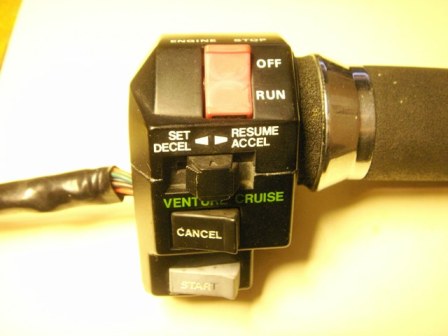
 I am in the process of installing cruise control on my 1983 Venture Standard. I have purchased almost all of the items I need to do this upgrade from ebay. Prior to installing the parts, I will be disassembling the ones that I can and cleaning them. I have made the following write up of the process of cleaning the clutch side switch housing that came off of a 1988 Venture. The pictures show the switch completely removed from the bike. It is fairly lengthy, 47 pictures, but thorough. I would recommend removing switch from bike if you perform this cleaning. There are a number of small springs and ball detents that are very easy to lose unless you have a large well lit working area. If you are unable to open the PDF file, PM me with your email address and I will send it to you. I have detailed the throttle side switch in another thread. Picture below is of the switch detailed in this PDF file.
 -
I am in the process of installing cruise control on my 1983 Venture Standard. I have purchased almost all of the items I need to do this upgrade from ebay. Prior to installing the parts, I will be disassembling the ones that I can and cleaning them. I have made the following write up of the process of cleaning the clutch side switch housing that came off of a 1988 Venture. The pictures show the switch completely removed from the bike. It is fairly lengthy, 47 pictures, but thorough. I would recommend removing switch from bike if you perform this cleaning. There are a number of small springs and ball detents that are very easy to lose unless you have a large well lit working area. If you are unable to open the PDF file, PM me with your email address and I will send it to you. I have detailed the throttle side switch in another thread. Picture below is of the switch detailed in this PDF file. 38050.pdf
-
Cruise Control Question
dingy replied to Evan's topic in Venture and Venture Royale Tech Talk ('83 - '93)
Evan, Attached is PDF file with a large red arrow on right side showing where to connect a volt meter at to check for steady voltage on cruise circuit. As Blue Giant and Camos said, play in switches at brake & clutch levers can cause this problem. This is the point in the circuit to see if that is what is happening. At the point shown circuit is also running through Cancel switch. Connect positive lead of meter at arrow & negative lead to ground. I have used a paper clip slid into back of wire connector to get a connection to wire being checked. The two places you can connect to this wire are behind head light in cable coming from throttle side switch or at the cruise vacuum pump. Both of these connectors are shown in the PDF file highlighted in red box at top of page. Wire you need to check is hilighted in red. It is a Black with red tracer out of throttle side switch or a Black with blue tracer at vacuum pump. You will be checking the voltage on the circuit just after it goes through the switches. After hooking meter up and turning the key to the On position, wiggle the levers and see if you get any voltage fluctuations. Also check cancel switch. -
Is it possible to send an attachment via the built in Email function on this site? There have been a few people that have had difficulty opening the PDF files that I have posted in the past from the site. When I email them a copy it seems to work fine. An example is today Jimbob5 can not open the files in the Starting circuit thread I posted last night, but others can. I would email him a copy but first need to PM or email him for his email address rather than just being able to send it to him first time. Gary
-
Attached are redrawn schematics of the starting circuits for the 1st Gen's. I thought these might help people that have cranking & starting issues. There is a narrative above each circuit detailing operation. This text assumes a charged battery and intact fuses. There are three views of each circuit. Left side shows circuit in normal condition, key off, side stand down, transmission in neutral. Center view shows circuit with key on, transmission in neutral. clutch and side stand switches not shown as they are irrelevant in this configuration. All switches and relays shown in position to energize starting motor. RIght view shows key on, transmission in gear, side stand up and cluth pulled in. Neutral switch not shown as it is irrelevant in this configuration. All switches and relays shown in position to energize starting motor. Also, the side stand relay and Emergency stop sensor are shown. Neither of these affect the cranking circuit but will shut down the Ignitor unit. Actually, the bike will start and run with either of these pulled out. 84-85 one is almost identical to 86-93 version. Only difference is positive wire at starting solenoid coil. Gary
-
Attached are redrawn schematics of the starting circuits for the 1st Gen's. I thought these might help people that have cranking & starting issues. There is a narrative above each circuit detailing operation. This text assumes a charged battery and intact fuses. There are three views of each circuit. Left side shows circuit in normal condition, key off, side stand down, transmission in neutral. Center view shows circuit with key on, transmission in neutral. clutch and side stand switches not shown as they are irrelevant in this configuration. All switches and relays shown in position to energize starting motor. RIght view shows key on, transmission in gear, side stand up and cluth pulled in. Neutral switch not shown as it is irrelevant in this configuration. All switches and relays shown in position to energize starting motor. Also, the side stand relay and Emergency stop sensor are shown. Neither of these affect the cranking circuit but will shut down the Ignitor unit. Actually, the bike will start and run with either of these pulled out. 84-85 one is almost identical to 86-93 version. Only difference is positive wire at starting solenoid coil. 37977.pdf Gary
-
I am in the process of installing cruise control on my 1983 Venture Standard. I have purchased almost all of the items I need to do this upgrade from ebay. Prior to installing the parts, I will be disassembling the ones that I can and cleaning them. I have made the following write up of the process of cleaning the throttle side switch housing that came off of a 1988 Venture. The pictures show the switch completely removed from the bike. It is fairly lengthy, 41 pictures, but thorough. I would recommend removing switch from bike if you perform this cleaning. There are a number of small springs and ball detents that are very easy to lose unless you have a large well lit working area. If you are unable to open the PDF file, PM me with your email address and I will send it to you. Let me know if you find this helpful, as I also have the left side controls, brake and clutch switches I can do. Picture below is of the switch detailed in this PDF file. 37950.pdf Gary

-
I am in the process of installing cruise control on my 1983 Venture Standard. I have purchased almost all of the items I need to do this upgrade from ebay. Prior to installing the parts, I will be disassembling the ones that I can and cleaning them. I have made the following write up of the process of cleaning the throttle side switch housing that came off of a 1988 Venture. The pictures show the switch completely removed from the bike. It is fairly lengthy, 41 pictures, but thorough. I would recommend removing switch from bike if you perform this cleaning. There are a number of small springs and ball detents that are very easy to lose unless you have a large well lit working area. If you are unable to open the PDF file, PM me with your email address and I will send it to you. Let me know if you find this helpful, as I also have the left side controls, brake and clutch switches I can do. Picture below is of the switch detailed in this PDF file. Gary
-
No power to bike
dingy replied to Bill Feehan's topic in Venture and Venture Royale Tech Talk ('83 - '93)
Attached is a PDF file cut from the shop service manual showing the start circuit for the 86-89 models. Gary -
Seems like 1554 rpm at 60 mph is low??? That's not much more than a fast idle. I have an 83 and I am around 3000 rpm at 50 mph
-
Seems right You might lose some people at the 790 revs of tire per minute. Mile = (5280 ft x 12inches) = 63360 inches per mile / 25.5 (dia. of tire) x 3.1414 (Pi) =80.11 (circumference of tire) = 790.91 revs per mile or 63360/80.11=790.91
-
Here are a couple of pictures of an 83 Non Royale trunk. No point. Gary
-
1st Gen Wiring Schematics 1983 - 1993
dingy replied to dingy's topic in Venture and Venture Royale Tech Talk ('83 - '93)
I have updated the schematics to help make them easier to read. All files are now on one sheet. I have eliminated the Audio sheet as Sheet #2, all Audio circuits are now shown on main page. I have staggered the wire color call outs where they are clustered together, such as by the instrument cluster connector. I removed the line types that had the X's & O's in them. These made it look like wires that crossed were connected in some places. I have added a legend to all sheets to help some people understand schematics a little better. Showed springs in the switches on simplified circuits to help clarify operation of switch. Only wiring change made was that the Emergency Stop Sensor was incorrectly shown as closed, it is now shown as an open contact. RSv version changed slightly as well. Hopefully this will be last change to them, I probably have a lot more than a couple hundred hours creating all of these. There are 16 different versions. Gary -
2nd Gen Wiring Schematics 99-09 RSV
dingy replied to dingy's topic in Royal Star Venture Tech Talk ('99 - '13)
I have updated the schematics to help make them easier to read. I have staggered the wire color call outs where they are clustered together, such as by the instrument cluster connector. Not much done to the RSV ones in general though. The 1st gens have been changed much more and they have also been updated. All files are now one sheet. Hopefully this will be last change to them, I probably have a lot more than a couple hundred hours creating all of these. There are 16 different versions. Gary -
Dover is very near what is called Amish Country in Berlin Ohio. Lots of small stores that are popular. Also there is a HUGE hardware store called Lehmans in Kidron Ohio http://www.lehmans.com/ They carry a lot of hand powered tools and related items. Very popular when Y2K was happening. Gary
-
neutral Light Illuminating constantly
dingy replied to Storminyte's topic in Royal Star Venture Tech Talk ('99 - '13)
I just looked at parts file for RSV and the switch & location look very similar to pictures in thread below relating to an 83 There is a PDF file at bottom of thread that has pictures in it. [ame=http://www.venturerider.org/forum/showthread.php?t=40639]Gear position Indicator upgrade for standard Ventures (Non-Royales) - VentureRider.Org[/ame] Gary -
Look at this thread for some info on neutral switch. There is a PDF file at bottom of thread that has some pictures of the switch and its home. [ame=http://www.venturerider.org/forum/showthread.php?t=40639]Gear position Indicator upgrade for standard Ventures (Non-Royales) - VentureRider.Org[/ame] Gary
-
Scooby Doodie Do is black & Tan Minature Pincher, 10 years old female. Dexter is Rust Minature Pincher, 6 month old male.
-
Do you want to be able to boot either your current OS or IE 7 ? Gary
-
2nd Gen Wiring Schematics 99-09 RSV
dingy replied to dingy's topic in Royal Star Venture Tech Talk ('99 - '13)
I just re uploaded the simplified schematic file & the wiring diagram file due to a cosmetic change in the way some wires were drawn. The same links in the top of this thread will now bring up the new & improved version. I eliminated the ones that had the X's and O's in them. I made up a different linetype to replace these. The new ones have one dot or 2 dots in them. I never really liked the X & O linetypes for a schematic. It made it appear in some places that two crossing wires connected. Problem is there are only so many linetypes with dashes and spaces available. I didn't change revision level for drawings as this is only a cosmetic change. Any one that does not like new style please return it with your receipt for a full refund. Gary -
2nd Gen Wiring Schematics 99-09 RSV
dingy replied to dingy's topic in Royal Star Venture Tech Talk ('99 - '13)
Drawn in AutoCAD 2009 Mechanical. Transferred to PDF via Any DWG to PDF Converer -
2nd Gen Wiring Schematics 99-09 RSV
dingy replied to dingy's topic in Royal Star Venture Tech Talk ('99 - '13)
Below is link to latest Adobe reader http://get.adobe.com/reader/ Ozlander used Foxit when he had trouble opening one of my first schematics. http://www.foxitsoftware.com/pdf/reader/download.php Gary -
Files Updated on 10/28/2009 Minor corrections done to both schematics. Text realigned for easier reading Gary I have completed the 1999-2009 Royal Star Venture schematics. The 99-09 Yamaha Royal Star Venture Wiring Diagram Rev B file shows all the connectors and resembles the wiring diagram in the 1999 Yamaha Royal Star Venture service manual that is referenced in the Second Gen and Royal Star Technical Library on this site. The 99-09 Yamaha Royal Star Venture Simplified Circuit Diagram Rev B file is the complete wiring for the bike in a much simpler format. Since the wiring connectors are not shown, components can be rearranged in a more logical format that reduces the wires running back and forth. Some of the switches are shown in a more convenient manner also. This file would probably be the one most used for trouble shooting. I have also added a legend to this group to help users understand the schematics better. If you find anything that needs changed on these schematics, let me know & I will fix it. The files will look best when plotted at 11" x 17" size or larger. Office Max, Kinko’s and Staples as well as others can do this for you for a minimal charge if you want a printout. I paid $1.00 for an 11" x 17" color print at Staples. All you have to do is take the PDF file that you download to their store and they can print it. Double click on underlined blue text below to down load the schematics in PDF format. Files were created in Adobe Acrobat 7.0. 99-09 Yamaha Royal Star Venture Wiring Diagram Rev B.pdf 1999-2009 Royal Star Venture From 1999 Yamaha Royale Star Venture Service Manual. Pages 9-7 & 9-8. PDF file pages 485 & 486 of 487. This file combines the MCU, Cruise Control Unit, Cruise switch & D.C. outlet systems on page #1. 99-09 Yamaha Royal Star Venture Simplified Circuit Diagram Rev B.pdf 1999-2009 Royal Star Venture I did this one from a blank sheet of paper. I could not find anything similar in the information I had available. 99-09 Yamaha Royal Star Venture electrical info.pdf This file is a compilation of various sheets from the 1999 Yamaha Royal Star Venture Service Manual that would be helpful when working with electrical system. They are not modified in any way, just as they appear in service manual.
-
2nd Gen Wiring Schematics 99-09 RSV
dingy posted a topic in Royal Star Venture Tech Talk ('99 - '13)
Files Updated on 10/28/2009 Minor corrections done to both schematics. Text realigned for easier reading Gary I have completed the 1999-2009 Royal Star Venture schematics. The 99-09 Yamaha Royal Star Venture Wiring Diagram Rev B file shows all the connectors and resembles the wiring diagram in the 1999 Yamaha Royal Star Venture service manual that is referenced in the Second Gen and Royal Star Technical Library on this site. The 99-09 Yamaha Royal Star Venture Simplified Circuit Diagram Rev B file is the complete wiring for the bike in a much simpler format. Since the wiring connectors are not shown, components can be rearranged in a more logical format that reduces the wires running back and forth. Some of the switches are shown in a more convenient manner also. This file would probably be the one most used for trouble shooting. I have also added a legend to this group to help users understand the schematics better. If you find anything that needs changed on these schematics, let me know & I will fix it. The files will look best when plotted at 11" x 17" size or larger. Office Max, Kinko’s and Staples as well as others can do this for you for a minimal charge if you want a printout. I paid $1.00 for an 11" x 17" color print at Staples. All you have to do is take the PDF file that you download to their store and they can print it. Double click on underlined blue text below to down load the schematics in PDF format. Files were created in Adobe Acrobat 7.0. 99-09 Yamaha Royal Star Venture Wiring Diagram Rev B.pdf 1999-2009 Royal Star Venture From 1999 Yamaha Royale Star Venture Service Manual. Pages 9-7 & 9-8. PDF file pages 485 & 486 of 487. This file combines the MCU, Cruise Control Unit, Cruise switch & D.C. outlet systems on page #1. 99-09 Yamaha Royal Star Venture Simplified Circuit Diagram Rev B.pdf 1999-2009 Royal Star Venture I did this one from a blank sheet of paper. I could not find anything similar in the information I had available. 99-09 Yamaha Royal Star Venture electrical info.pdf This file is a compilation of various sheets from the 1999 Yamaha Royal Star Venture Service Manual that would be helpful when working with electrical system. They are not modified in any way, just as they appear in service manual.