frankd
-
Posts
1,142 -
Joined
-
Last visited
Content Type
Profiles
Forums
Gallery
Events
Store
Everything posted by frankd
-

Exactly how do I jumper the CMS.
frankd replied to MasterGuns's topic in Venture and Venture Royale Tech Talk ('83 - '93)
Herb, You probably know by now, but yes, the LED will fit, and mine has a fan built in to it that cools the LED. Doug, I think that 84 and later CMU's are similiar, but 83's are way different. LEDs do make some heat, but no where near as much as an incandescent bulb. Frank -
If you're talking about the black component that is partially in the circle, it's a .047 microfarad, 400V capacitor. That TCI has been wet---the transistor mounting screws are rusty, and there is a section in the middle that has a lot of crud on it.
-
Exactly how do I jumper the CMS.
frankd replied to MasterGuns's topic in Venture and Venture Royale Tech Talk ('83 - '93)
In addition to Dingy's modification of the CMU, you need to dis-able the headlight module to turn out the white light and allow the LED to switch from Low beam to High beam. Here's how I did it. http://www.venturerider.org/forum/first-generation-venture-tech-talk/92344-installed-led-headlight-kit-89-a.html?highlight=frankd -
Soon I'll be going to my brother's house ab0it 160 miles south of here to install a replacement TCI unit in the 83. How much plastic do I have to remove to get the old TCI out? I've got the battery & battery box out, so unplugging the unit is easy. Every time I've ever pulled a TCI, I had the fairing off to do other things and was trying to remember if pulling the lowers and side plastic was all I need to do?
-
first gen am/fm power indicator on but no display
frankd replied to OutKast's topic in GPS, Audio, Electronics
Pull the radio console again and check if the cassette deck has come unplugged. Also verify that all 4 DIN connectors on the main chassis are plugged in completely. If you know anybody with a 1st. gen. Venture, swap control units and see which half has problems. -
Side panel vents...
frankd replied to mechanic1's topic in Venture and Venture Royale Tech Talk ('83 - '93)
I would also be interested in a set, if they open and close. -
Vacuum advance restrictor
frankd replied to frankd's topic in Venture and Venture Royale Tech Talk ('83 - '93)
Gary, Did you restrict the connector or just install it as is? If you filled in the connector with something, what did you use? I'm considering a blob of RTV type instant gasket/sealant with a toothpick pushed through it. Then when the sealant cures a bit, just rotate the toothpick and remove it leaving a small hole. -
The TCI module on the 83 took a dump, and finally I was able to purchase an 84 TCI for a fair price. This was the 2nd one I purchased. THe first was for an 83, and my 89 only ran on 1 cylinder on it. When I opened it up (after getting my refund--the seller didn't want it returned) it was extremely wet inside. Now I need to change how the pressure module is piped to the engine, but I don't think the 83 has a restrictor. The bike is at my brothers 160 miles from here, so I can't just run out and look. I looked in the Yamaha parts list, and couldn't find the restrictor listed. I have some questions...... 1) Does the 83 already have the restrictor? If it does then I have everything I need. 2) Where is the restrictor listed on the parts fiche? I looked on 'Electrical 2' where the pressure sensor is and also on 'Carburetor'. I didn't see anywhere else that I thought would be where they hid it. 3) Does anybody have an extra restrictor? Thank you, Frank
-
Randy, On a MkII, both anti-dive solenoids are energized whenever the brake light is 'ON'. I've also been thinking of adding a Time Delay Relay (TDR) to mine, but haven't done it yet. How much current is the TDR rated to switch. I think to avoid doing damage to the TDR, that I'd add a diode (IN4001 or similiar) in parallel to the anti dive solenoids to limit the arc across the contacts of the TDR when the contacts open. Connect the diode's band (the cathode) to the lead to the solenoids and the other end to ground. Measure the resistance of the solenoids so we can determine how much current they'll draw to verify that you will not be overloading the TDR. MKII bikes have a relay for the solenoids, so on MKII's we could wire the TDR to the relay coil and not worry about overloading it. I'll have my bike started late next week, so I can measure the solenoid current with my clamp on DC ammeter. I'll get back to you on this. Frank
-
The reason you probably couldn't find it was that I did mine for an IPOD, but it'd work just fine with an MP3 player. http://www.venturerider.org/forum/radio-cb-gps-etc-/44070-tape-deck.html?highlight=frankd+ipod The treble response is a bit hot with this system, so I just set the equalization on my IPOD for "small speakers" (treble cut, bass boost), but if your MP3 doesn't have this function, you could just put a small capacitor across each input to the amplifier. You'd have test different values of capacitors to determine the correct value. Rick, I think this is for a 1st Gen., so there is no OEM jack! Frank---KA9J
-
Most vehicles of this age feed the temperature sensor signal into the engine computer, and the computer has an output that connected to the temperature gauge. Seeing that your odometer also stops working, I'd suspect a problem in your dashboard itself. Try lightly taping the dashboard the next time one of them takes a siesta. Also you could try 'GOOGLING' the problem (search for 2004 F150 temperature gauge" and see what you come up withl
-
Ignition woes (maybe)≥÷
frankd replied to flyday58's topic in Venture and Venture Royale Tech Talk ('83 - '93)
If your regulator got warm, your stator is producing power. A long time ago, I had a similar problem with my 83. I measured the voltage at one of the red wires coming out of the regulator with the engine running. On mine it measured normal (14.5V plus or minus .5V) but at the battery I had less. I found the mounting screws for the main fuse link were a bit loose, causing a high resistance connection. Tightened them up and everything was fine. The main fuse is on the left side of the battery, and get to the fuse link, you have to open the housing. After you get it apart, loosen both mounting screws and then re-tighten them and that will clean some of the oxide off the connections. -
Ignition woes (maybe)≥÷
frankd replied to flyday58's topic in Venture and Venture Royale Tech Talk ('83 - '93)
The regulators on Gen 1s are pretty durable. I have seen one bad, but stator and connector problems are much more common. Unplug the white wires from the regulator and inspect them carefully and make sure none are burnt. Take an ohmeter and measure the white wires going to the stator. All 3 combinations (1-2, 2-3 & 1-3) should measure equal to each other. Touch your meter leads together, and read you ohmeter. It'll probably indicate .1 or .2 ohm. This is the resistance in your meter's leads, and you need to subtract this reading from the measured resistance from the stator leads. BTW, spec. for this is .42 ohm @ 68 degrees F. Then put connect your black ohmeter lead to engine ground and the read lead to one of the white stator leads---this should measure open (infinity). If your stator passes these tests, it still may be bad. With the regulator plug still disconnected, start the bike, and have somebody watch the tach and hold the bike @ 2000 RPM. Put your meter on AC volts, and measure the voltage between the 3 pairs of white wires---The should be approximately equal. If one set measures 80VAC and another set measures 15VAC, you have a shorted turn in your stator (bad). -
Also, oxygen sensors don't like antifreeze being burned and passing over them. I'd wait until you fix the head gasket leak and make certain that everything looks OK before worrying about it. When you pull the heads (and you are pulling them both, aren't you?) look at the combustion chambers in the heads. If a cylinder has had coolant in it, it will look cleaner than the rest. Rock Auto is a good place to get the O2 sensor also. Frank
-
Also with 90K on a 3.0 Mitsubishi, it's time to replace the timing belt. This is an 'interference' engine, which means that if the cam and crankshaft get out of time, a valve could hit a piston.
-
Yes, that is the show and the roads I was talking about. I'm not sure if we'll be going this year or next year. Our friends have a lot planned for this summer with their camper and we may not be able to squeeze this in. But I really want to do this!!!!
-
I woke up this morning (New Years Day) and laid in bed thinking about things, and a trip that I've been thinking about took the stage. I'm sure that most of you have watched episodes of "Highway Thru Hell" on The Weather Channel------I've been thinking about riding some of these roads, but of course in July or August. Do any of you live or at least ridden around the 'Highway'? We've gotten our friends interested in this also, but he added heading up NW so we can touch the south tip of Alaska also. It'll be a long ride (we live in Illinois) but it should be beautiful. I'm also thinking about the actual route we'd take to get to and from where we cross into Canada so we can see some new things. Frank
-
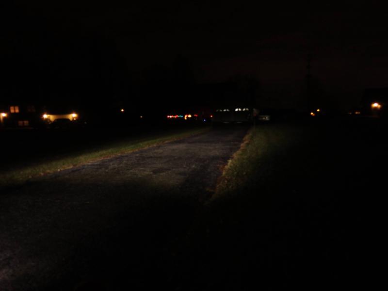
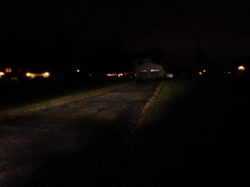
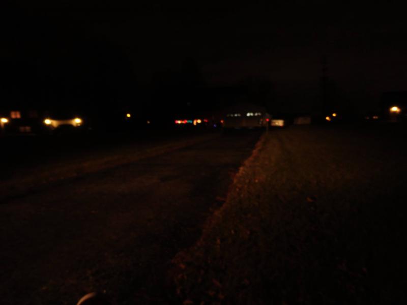
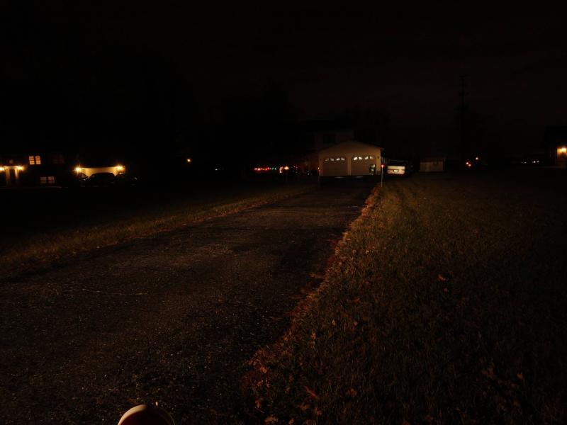
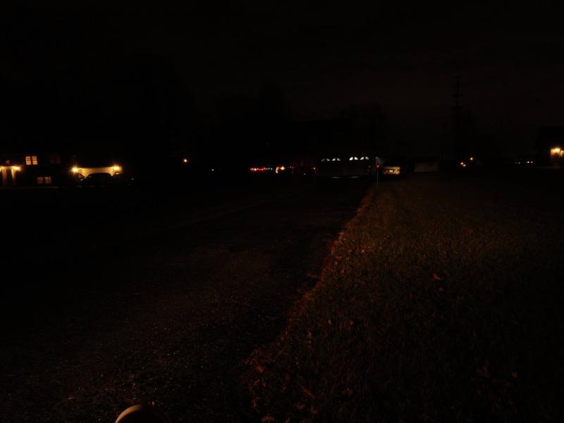
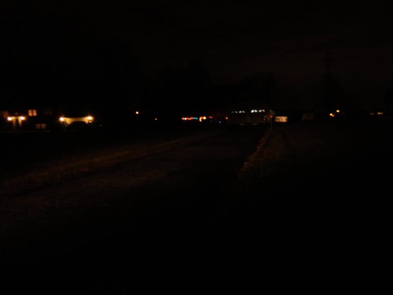
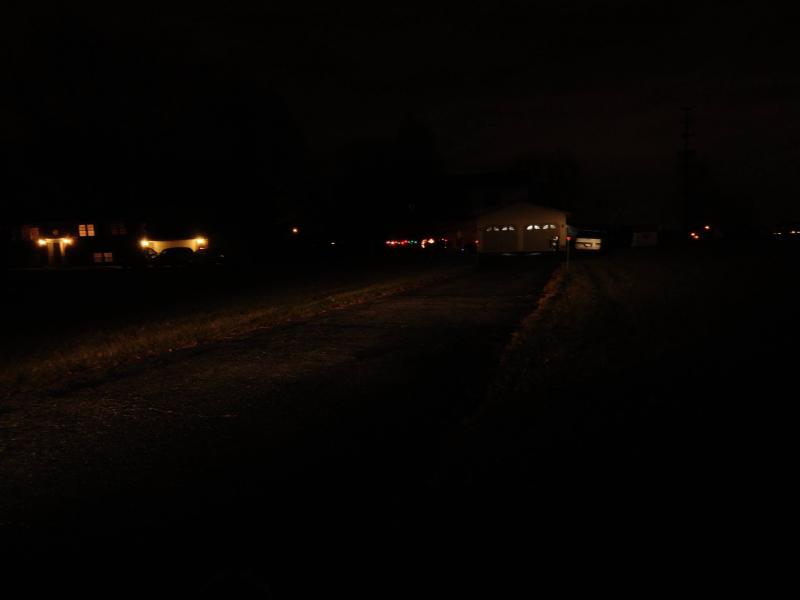
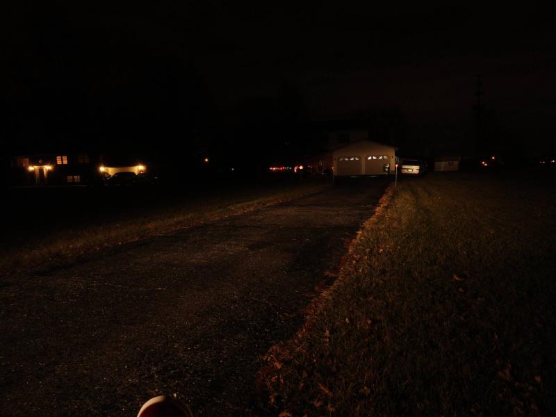
The weather has gotten much better here and my son-in-law was here to help me push the Venture around and help me with some pictures of the LED headlight. The LED headlight looked pretty good compared to my Ford FreeStar with regular halogen headlights. The pictures show the bike on low beam, then on high beam. Then you'll see the FreeStar on low beam, and then high beam. Then with the left headlight blocked followed with the right headlight blocked (low beam) and the right headlight blocked high beam. Then both high beams again. It's probably about 160' to my garage. The LED headlight looks better than I thought when I first rode at night. I also have LED driving lights on my bike (they were off for the pictures) and the dark area close to the bike would be quite a bit brighter with them on and aimed low. The pictures were taken with identical, fixed exposure and aperture. Frank

-
Also, is it cranking normally, or does it sound like it's spinning faster than normal?
-
Well, I didn't ride too much, but I did get down some dark county roads. Probably some of the reason the head light doesn't seem to change too much is that when you switch to high beam, the low headlight stays the same and some additional light is added on the top of the beam--it looks like they switch on an additional section of the LED bulb. The kit is rated 2200 lumens low beam and 2400 high. Yes, I'm happy so far, but I only had the bike out for 2 short rides. When you say that it looks like a 2 prong connector, I imagine your talking about the headlight connector. No, it's uses all 3 leads of the original headlight connector. The original headlight connecdtor plugs into the LED's controller module, and then another cable comes out of it and goes to the LED. If it ever quits raining and the wind lets up a bit, maybe I could take some pictures of the light pattern on my garage door and compare it to the pattern of a car headlight.
-
First Gen Ventures don't absolutely need a 'thinwalled thingy' to pull the plugs. An 18mm 3/8" drive deep well socket and extension will work. Just be careful to keep it squarely on the plug so you don't break the plug's insulator. If you have an air compressor, blow the area around the plugs out before you pull the plugs. If the carb bowls are full of fuel, you won't hear the fuel pump cycle. It only clicks when you need fuel in the carbs. If there is any doubt that there isn't fuel in the carbs, you could pull a carb drain screw and see if fuel runs out of the hose below the carbs. Just make sure you have the correct #2 phillips screwdriver. I don't know what shape they are in your area of the world, but American phillips screwdrivers have a slightly different shape than Asian philllps screwdrivers. The reason I say this is because if you use the wrong phillilps it won't fit the screw properly and you probably will strip the screw head. An Asian phillips screwdriver fits much tighter in the screw head. Are you using the correct proceedure to start it cold. Also how cold is it where you're trying to start the bike? If it's about 0 Celsius, you'll probably need full choke and no throttle to get it to fire. On my 83, as soon as I hear the first cylinder fire, I blip the throttle, and it starts right up. If it's warmer, try about 1/2 choke. If you've flooded the engine, turn the choke completely off and rock the throttle from idle to about 1/2 back and forth as you crank the bike for about 15 seconds. Then close the choke about 1/2 way and try a normal start. My 89 (different carbs than the MK I bikes) starts much better.
-
Guys, he said that the bike cranks, and the kill switch, and the side stand switch stop the bike from cranking, so they can't be the cause. Have you checked for spark? Pull a plug wire, and put an spare sparkplug in it, hold it against the engine, crank the engine, and watch for spark.
-
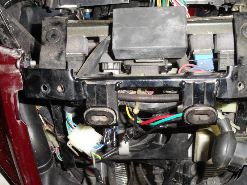
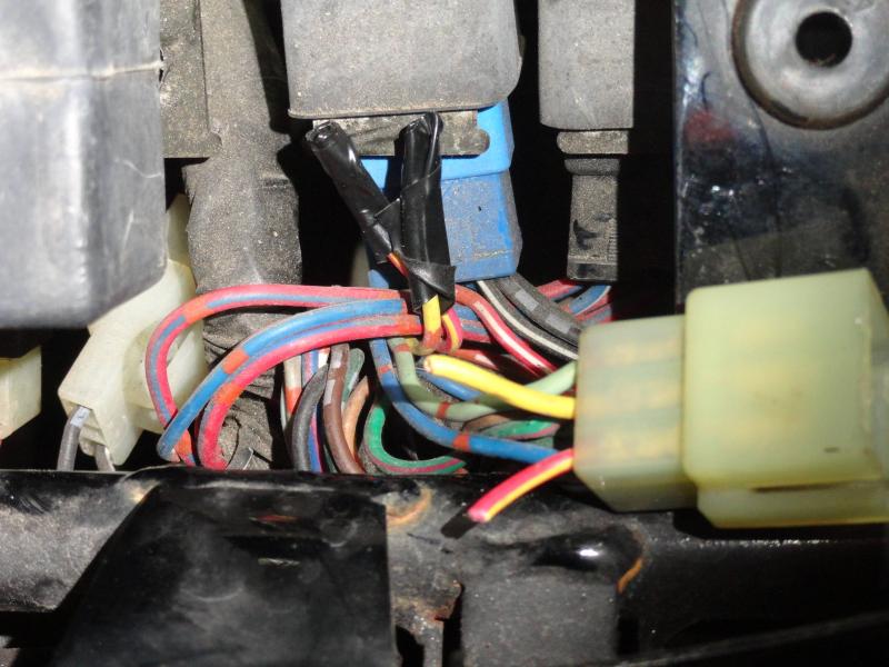
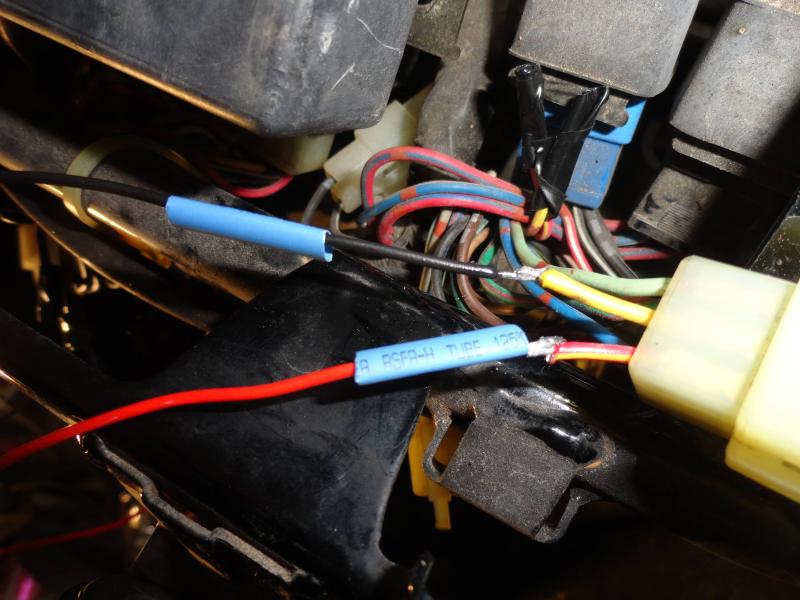
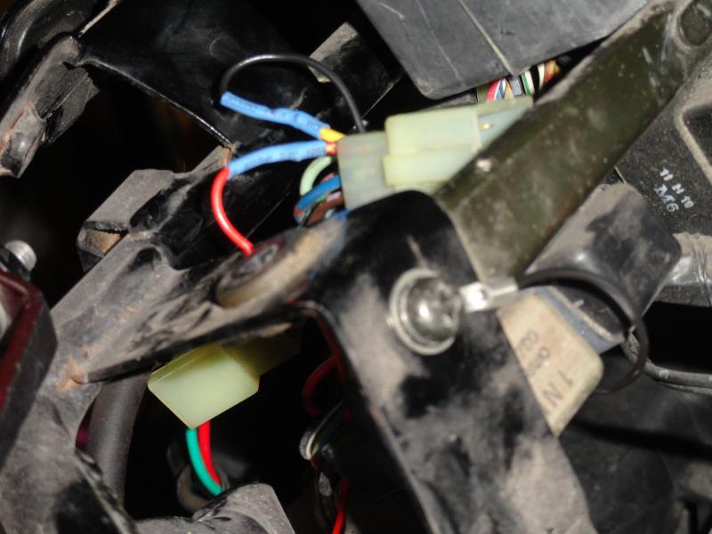
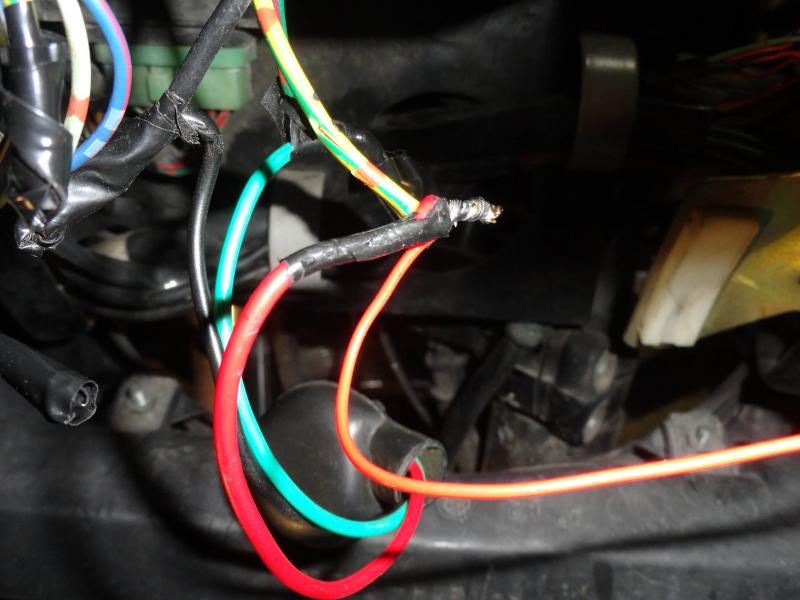
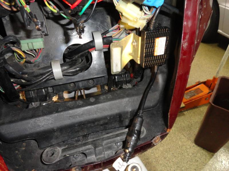
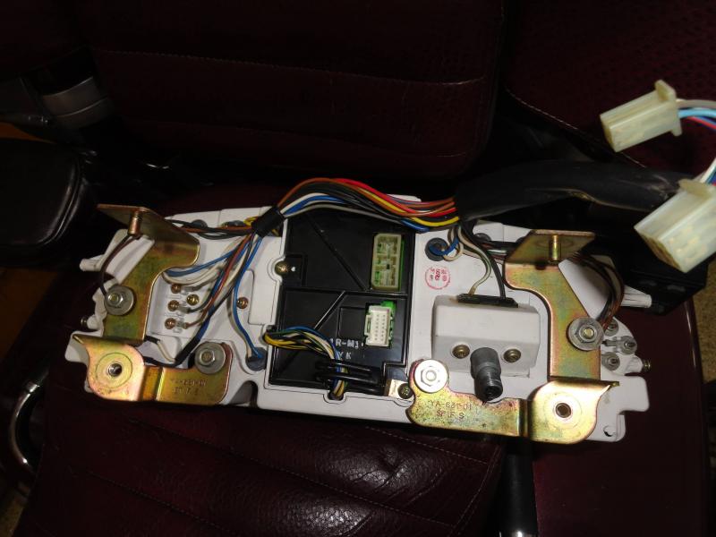
I just bought the SpeedMetal 2200/2400 Lumen LED headlight conversion kit from CycleGear for $60. I don't know he long they'll have this sale, but they have it every so often. I wondered about the light pattern, so I removed the headlight from my bike and took it down to my workshop. I used a big wooden 'C' clamp to position it in a repeatable position. Before I took the Sylvania Silver Star bulb out of the headlight, I applied 13 volts to it and observed the light pattern on the basement wall. I marked the top of the main part of the light beam with a marker, and then repeated this with the high beam. I also marked the workbench where the 'C' clamp was so that I could put it back in the same position. I switched to the LED lamp and powered it up. There appeared to be very little difference in the beam shape or position, but of course the light beam was much brighter. The light beam on low was just a tiny bit higher, and the high beam was more than a bit higher. It looked great. I connected it to the bike, and I had the headlight alarm in the CMS on, and I couldn't switch between high and low beam. Dingy recently showed a picture of the CMS printed circuit board and also where to jumper to eliminate the alarm. http://www.venturerider.org/forum/first-generation-venture-tech-talk/92274-jumper-cmu-leds-bulbs-prevent-warning-light-coming.html Of course, the instrument panel has to be removed from the bike first. It's not a bad job, just take the windshield off and take the screws out for the front turn signals and let them hang by the wires. Look inside the turn signals mounting at the openings to the sides of the instrument panel. On each side you will see 2 phillips screws that hold the instrument panel cover to the instrument panel. Take the 2 that prevent the cover from sliding upward completely out, and loosen the 2 screws that prevent the cover from sliding toward the rear of the bike. Then just slide the cover toward the rear of the bike. To remove the instrument panel, using a 1/4” ratchet, long extension, universal joint, and 10mm socket, reach upward from the headlight opening and remove the 2 bolts from the bottom of the instrument panel. DO NOT REMOVE THE NUTS---they just hold the brackets to the instrument panel. Also when I had the bolts out of the threads, but still in the hole, I reached in from the top with a magnet tool and prevented the bolts and washers from falling when I pulled the socket off the bolt. Looking through the headlight opening, towards the left side of the bike (look right into the opening) you will find 2 connectors for the instrument panel---disconnect them. Disconnect the speedometer cable, and then pick up the instrument panel slightly to slide the top pins out of the grommets, and move the panel towards the rear of the bike slightly. Reach in and disconnect the 2 connectors on the back of the CMS (BTW, CMS=Computer Monitor System). Now remove the instrument panel. Place a soft cloth on the work bench and set the panel down face down. Take the screws out that mount the CMS, and remove the CMS. Take it out as 1 piece, there is no need to slide it apart yet. Lift the side that has the wire bracket under a screw first, and then when it's clear of the hole, slide it towards where the wire bracket was mounted. You'll see that the other side has a clear plastic piece on it that allows the panel bulb to illuminate the CMS. Separate the CMS but be careful. One board has a connector that can be pulled to separate that board. However 2 boards have a ribbon cable that you can't easily remove, so don't stress this area too much. The CMS light monitors have a magnetic proximity switch wrapped with a coil of wire. The lamp current flows through the coil, and creates a magnetic field, that closes the proximity switches. You need to solder a small piece of wire across the proximity switches for high and low beam headlights. Dingy has arrows pointing to the correct places to put the jumpers. Then re-assemble the CMS and re-install it in the instrument panel. (see picture of the back of instrument panel) (See picture #1) You can see the RLU (Reserve Lighting Unit) at the top of the picture. Follow the wiring out of it to the connector. On the motorcycle side of the connector, cut and tape the G/R, Y/G, and the light green wires (the light green isn't shown in the picture). Now, you'll be able to switch between high and low beam, and the HEADLIGHT white lamp on the instrument panel won't come on, but the blue high-beam light on the instrument panel won't work. To get that working, on the motorcycle side of the instrument panel connector, cut the Y and the R/Y wires leaving about 2” of them still on the connector. Tape the 2 wires not in the connector (that you just cut). Using two 12” lengths of 16-20 gauge connect them to the Y and the R/Y wires from the connector. I soldered mine and used shrink tubing to insulate them, but you could use butt connectors. (picture #2) Connect the Yellow wire to ground. I used a terminal and put it under the screw in the picture (picture #3). Shorten the wire before putting the terminal on it. Connect the R/Y wire to the headlight high beam lead (Y/R). On my bike, I've replaced the headlight socket, so I had soldered and taped connections to the new socket. I just untaped mine, wrapped the R/Y around the previous connection, soldered it and then taped it again. If you still have the original headlight socket, use a pocket knife and strip a short length of the Y/R wire, wrap the R/Y wire around the bare wire, solder it and tape it. (picture #4) This completes the necessary wiring changes and your LED headlight should work on both high and low beams, and you should have no alarms. Also, your blue high beam light should work. Now you need to mount the LED light control module. In picture #4 you can see where I mounted mine. Then when I was installing the headlight into the bike, I saw that the control module was hitting the side of the headlight. I ended up using a heat gun to get the double sided adhesive pad to release and then I moved the control unit about 1/4” more to the left side of the bike. The connector between the LED bulb and the control panel has a lock nut, but on mine the lock nut wouldn't stay tight. To cure this, I wrapped the connector with electrical tape to prevent the nut from loosening. Now it's time to install the headlight. Position the original headlight and the LED to control module wiring so that they won't get pinched by the headlight and the height adjusting mechanism. Last night I rode the bike for a bit to 'test' the headlight---Low beam was a lot brighter than the OEM bulb, and the pattern seemed a bit wider. Nobody flashed their lights at me though. It's not a road burner. However when I rode along side of a car with halogen headlights, his beams looked like they were made by candles. The high beam wasn't that much better than the low beam. The high beam pattern seems to be pretty high.
-
Getting harder to start
frankd replied to dna9656's topic in Venture and Venture Royale Tech Talk ('83 - '93)
With 4000 miles on the plugs, they should be fine, but new plugs will definitely help. Your engine filling up with unburned gas when you use full choke points to weak spark. My 83 has had this problem since it was new. One way I found to help was to use about 1/2 choke, and then started to crank and when I heard 'life' (a cylinder firing) I blip the throttle. The bike usually starts great. There have been times that I've had a terrible time getting it started though. If I think that it's become flooded, I turn off the choke, and crank it while I roll the throttle open and closed. Sometimes this makes it start. If not, I turn on about 1/2 choke and start all over. If it's about 40 degrees, I use full choke. Here's something else to check......Seeing that a new battery and new plugs help so much, making the spark stronger will do wonders. Venturous Randy found something that would help this problem. He found that on his 83 that when he was cranking it over, the voltage going to the TCI went way down and the spark was weak. He added a relay that used the red TCI lead for the relay's coil and wired it so that the relay contacts switched a better source of voltage to the TCI. Now, I haven't done this mod to my 83 because my brother is using it, and he never rides in cooler weather. Take a DC voltmeter and if your TCI is in the stock position, use a pin to puncture the TCI red wire's insulation. Connect the red meter lead to this pin, and the black meter lead to ground. Crank the engine over and read the voltage. Then move the meter's red lead to the battery and repeat the test. The difference between the two readings is the voltage drop in the bike's wiring harness. Now Yamaha changed a lot of the wiring in both the 84's and 85's compared to the 83's. You probably will have to pull the battery and battery box to get to this, but to test it just set the battery on the frame brace that holds the battery box. Mk II bikes are different yet, and they don't seem to have this problem. My 89 starts great, even with worn spark plugs and a battery so weak that it'll hardly crank the bike over. I searched for Randy's message, but it didn't jump out and grab me. He's changed his handle though and I may be looking for the wrong one. Maybe he'll jump in here and let you know exactly how he did this. If not, I'll search more or write a detailed message that tells you how to do this step if it's necessary. Something you could do to tell if this will help your bike.....Using the pin in the TCI red wire, connect a jumper to it. Be careful that it doesn't touch ground or you'll blow a fuse. Turn the key ON and connect the other end of the jumper to your batteries positive terminal. Then see how well your bike starts. -
Charging system not working
frankd replied to rougeray's topic in Royal Star Venture Tech Talk ('99 - '13)
Is your battery fully charged? If not, please charge it fully, and then with your charger set to it's lowest range (2 Amp), measure the voltage across the battery. Hopefully it'll be near 15 volts. This will verify that your battery can accept a charge without loading down the charging system. Your readings of .07 and .06 VDC drop on the wiring from the regulator to the battery seem good now.