dingy
-
Posts
5,403 -
Joined
-
Last visited
Content Type
Profiles
Forums
Gallery
Events
Store
Everything posted by dingy
-
WHY would we need to click more to get to the the icons that let us go to the second page. And not wanting to sound like a grumpy old fart, but I direct your attention to the first post in this thread titled "Why click on more" Hey Mini, PM me, I got some ideas for you !! The heck with watching you mini, I got your back girl !! Gary
-
This is not fair, You did increase it to 20 posts, but we still have the MORE button. Probably part of the javascript coding. Since the more button is still here, I may be somewhat less diligent on the Muffin patrol, I promise to keep you informed, if I have any verifiable, high confidence intel on any devious plans though. Gary
-
Please change it to 20 !! I would even volunteer to be on Mini Muffin watch at next MD for you !! (Didn't say I would stop her though) Gary
-

Help-valve shim tool
dingy replied to dug050's topic in Royal Star and Royal Star Tour Deluxe Tech Talk
I think maximum deflection of the buckets would be around 130 deg rotation. This is from looking at the drawing I did. As it rotates past 90 deg, there is still some increase in the outside radii, even though the inner machined radii have been passed by. Gary -
Help-valve shim tool
dingy replied to dug050's topic in Royal Star and Royal Star Tour Deluxe Tech Talk
OK, I am officially bored with winter. Below are a couple of quick drawings of tool in two positions. First is tool inserted over cam. Second is cam rotated 90 deg and tool pushing down on buckets. Cam lobes are rotating up and to rear for reference. This is showing the 'B' version of the tool, with the shortened long leg. This is explained in post #13 above. Gary http://i1007.photobucket.com/albums/af193/gdingy101/toolinserted.jpg http://i1007.photobucket.com/albums/af193/gdingy101/toolandcamrotated.jpg -
Help-valve shim tool
dingy replied to dug050's topic in Royal Star and Royal Star Tour Deluxe Tech Talk
I don't think you could over rotate it and have the valves snap shut. As you insert the tool, the short leg is down and engages the buckets, as the cam is rotated, the buckets are increasingly depressed as the tool rotates towards the long leg, with contact being made on the smaller radii machined into the face of the tool. Maximum depression of the buckets occurs when the long leg of the tool is vertical. At this point the buckets are contacting the tool half way around the rear of the tool. Over rotation would try to force the longer leg through the bucket contact point. I don't think this would be possible, at least without some serious damage to tool, cam or buckets Gary -
$5,000 for all the panels. Gary
-
Actually he is an upbeat person in general. He is in his late 30's. I was some what surprised by the theme. But it is not like skulls and that stuff. He didn't actually specify the exact scope of the airbrushing. The painter used his artistic skills for the specifics. My cousin, actually it is my cousins son's bike, picked out the themes for each panel and the general idea. One of the panels has Vincent Price on it, so that sort of leaves out the younger group. He is just a fan of horror movies in general. Bike was the bright HD orange 2007 model, always called it a pumpkin, so the Halloween theme sort of blended in with the color. Gary
-
battery tender hook up
dingy replied to Sandbagger's topic in Royal Star Venture Tech Talk ('99 - '13)
Positive (red lead 99.99% of time) to positive battery terminal. Negative (black lead 99.99% of time) to negative battery terminal. Running negative to a frame ground will work, if it was mine I would go to battery. You already need to run positive there, might as well do both. If you still are not sure, use a meter. If you don't have one, they are cheap, Harbor Freight has one for under $5. If your not sure how to use a meter, PM me, I will try to help. Gary -
Mythbusters featured products like this on one of their segments and they seemed to have almost no effect from what they aired on TV. Gary
-
Below are some pictures of the first four panels from my cousins HD Road Glide. All are being done in a horror film/Halloween theme, with a different theme on each panel. Though side covers, which appear to both be pumpkins. Most of the characters in the panels have been modified to resemble Hogs. The left side of the tank is Freddie Kruger, but with hog features. Not for most people, but what he wanted. There is some extreme detail in theses. The guy that is doing them has put about a week in the tank alone. His bike is the orange on on the right in the last picture as it was. Gary
-
Help-valve shim tool
dingy replied to dug050's topic in Royal Star and Royal Star Tour Deluxe Tech Talk
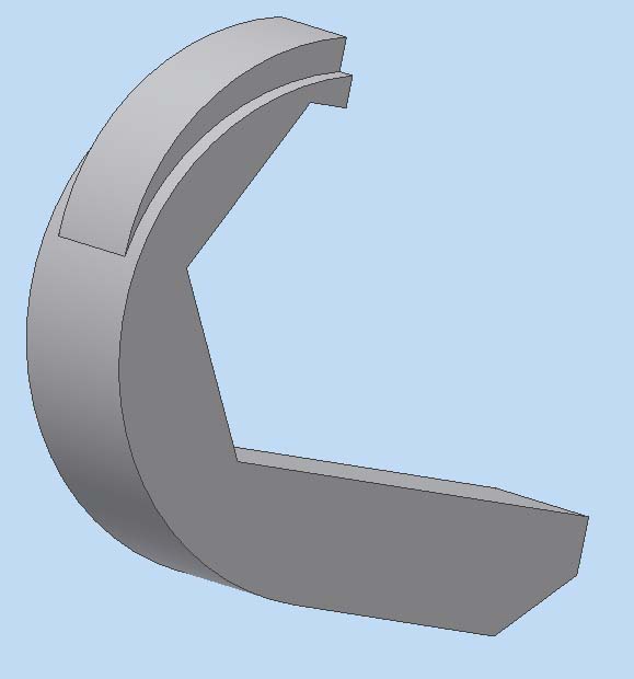
Carl, What I showed on the B rev drawing is to eliminate the chamfer by shortening the long leg of the tool to the point where the chamfer started. I just updated the two drawings in the first post, so the dimensioning styles matched, one was done in coordinate layout, and the other, point to point style. Now it is easier to see changes. I did not feel the shortening of this leg would adversely effect the tools functioning, yet still allow for it to clear the head. I posted a picture below to illustrate the point in question. 2nd picture shows tool rotated and chamfer clearing head. The reason I showed this is that in order to produce this tool in small quantities, it will have to be CNC machined. With the chamfer on the end as it was, it will take a very short, special clamp, to hold it on the CNC table vertically. This would be required to allow the cutter head to be able to cut the back arc, then cut the chamfer in one machining setup. It can be done in two setups, but that then increases the cost of the tool. As it is, the blank will need to be milled down to the required thickness (.425") in one machining operation. Then be positioned in a CNC machine to cut the profile out. Even at that, it would require a 5 axis machine, I think. There are also added relief cuts (.031" R.) at the two corners of the hex that fits around the camshaft. This is to allow a CNC cutter to cut the flats. This may need to be increased to .062" depending on tooling availability. As the tool is made now, I believe it is a forging, with no secondary machining done to it. That would prohibit making this tool in small quantities economically as it is now designed. Gary -
Help-valve shim tool
dingy replied to dug050's topic in Royal Star and Royal Star Tour Deluxe Tech Talk
The 'B' version of the drawings I posted above does what Squeeze is suggesting. I increased the downward movement of the shim bucket by about .015". It also has .031" reliefs in the corners of the hex shape for tooling clearances. Gary -
Help-valve shim tool
dingy replied to dug050's topic in Royal Star and Royal Star Tour Deluxe Tech Talk
Attached is a drawing of the tool, if you would like to take a shot at making one. Dimensions taken from an official Yamaha tool for the first drawing. Second drawing, Valve Shim Tool Rev B.pdf, has been modified slightly to make it easier to machine. Still same functionality though. Second one I showed being .010" wider as well, this was to center between shim buckets better. Not sure about the material spec of 17-4 steel, but that would be my choice for hardness & machining. I just reloaded the two drawings, I matched the dimensioning styles between the two so they are easier to compare. If any of the CAD equipped people want the model of the tool or draft files let me know. Gary 53261.pdf
-
I need a part number
dingy replied to ragtop69gs's topic in Royal Star Venture Tech Talk ('99 - '13)
I believe it is part #9 on attached link to partshark.com http://www.partshark.com/fiche_section_detail.asp?section=39081&category=Motorcycles&make=YAMAHA&year=2001&fveh=1032 It is on the crankcase page. PLUG,SPEC'L SHAPE 90338-11152-00 Gary -
intake question
dingy replied to kevin-vic-b.c.'s topic in Venture and Venture Royale Tech Talk ('83 - '93)
They are listed under the Air Filter section. Joint, Carb. I think MiCarl selles them, look in classifieds under 1st gen, Vendors. Or here is link to his site: http://store.thundervalleypower.com/ I also have some cracks in mine, but they do not go all the way through. Just minor outer layer cracking. Gary -
Are there any downside issues???
dingy replied to MasterGuns's topic in Venture and Venture Royale Tech Talk ('83 - '93)
Would had posted on the original thread by Skydoc but thought it would be best to start a new one. I have been considering purchasing the anti-dive blocking plates from Skydoc; essentially removing the anti-dives system from my 86. Can't really think of a good reason in doing so otherthan eliminating the needed power they require. Already have the Progressive springs installed. So, I have the following questions. 1) Does the anti-dive system draw any power when the front shocks aren't under an increasing load (diving)? Anti Dives are only engaged when front or rear brake is depressed (same circuit as brake light activates Anti Dives) 2) How much power does the anti-dive system draw when the front shocks dive (max draw)? I will check later today, but I think it is around 5 amps when brakes are activated. 3) By making the front shocks stiffer which reduces the dive, doesn't that fact alone reduce the amount of juice the anti-dive system draws? No, Anti dives are either on or off, the Anti Dive on an MKII is a solenoid valve (similar to a relay), there is a coil, that when activated, moves a plunger in the Anti dive valve body. 4) And I suppose that by eliminateing the anti-dive system, that doesn't eliminate the ability to use the CLASS up front (increase/decrease air pressure). No, Class system is entirely separate system. CLASS helps to stiffen front and rear end. Depending on bike weight and road conditions, the amount of air in the shocks is varied to change riding stiffness. 5) Last question. As all us 1st Gen owners know, whenever the rear brake is applied, which activates two 1157 stop light bulbs, is when the voltmeter really drops. Whether stopped or moving, activating the rear stop light affects the voltmeter the same. I've installed a couple really good bright 260 degree LED bulbs in the tail light and notice my voltmeter doesn't drop one little bit when activating the rear brake. Having said that, I doubt the anti-dive draws much at all. The question is: Could some convince me that removing the anti-dive is really a good idea? If you have progressive springs, I believe the anti dives are useless. I am working on a drawing that shows the fork system in detail, and from what I can see, the anti dives do nothing prior to the last 1" of fork travel, just before it bottoms out. The drawing below is still not complete. I am waiting to get an inner fork tube and an MKII electric Anti Dive valve from MiCarl next Saturday. It has an MKI Anti Dive valve which is similar to the MKII unit, except it is activated hydraulically. Some components still need to be adjusted, but for the most part it is close. The purple bushing inside the inner tube still needs work. Gary http://i1007.photobucket.com/albums/af193/gdingy101/Forkcomp-ADclosed.jpg Below is a view similar to the one above, but with the fork at 1 1/2" from bottom. At this point, both of the ports in the Anti Dive valve into the outer fork tube are unrestricted. By this I mean that both ports are going into the same cavity in the tube. If they are going into the same cavity, I can see no effect that they can impart on the fork. It is not until the fork travels slightly more downward, that the lower bushing on the inner fork tube passes by the upper port on the Anti Dive valves that any thing can begin to occur. http://i1007.photobucket.com/albums/af193/gdingy101/ForkTubeat11-2inchalt.jpg -
OK, that should be worth $12 to you then. One year membership of somewhat knowledgeable help, free sarcasm, and a bunch of good people that will try to help. Gary
-
From the album: Rebirth of an 83 Venture
-
Sorry, I should stick to 1st gen help. But, really, I was working with Ponch on several phone calls, and I thought he said part of what we were working on was under the seat. We were trying to get the hazards to work without needing the key to be on via some circuit modifications. Gary
-
The seals are located at a point in the shock system that should always have oil above it, this is of course inside the inner fork tube. That being said, you would almost certainly have a noticeable oil leak, prior to anything serious enough to suck air into the system. Are you noticing the air build up after riding? It could be that due to heat buildup inside the forks, the oil is expanding slightly, giving a higher pressure reading when warm. Is the oil level identical between the two forks? A difference in oil height could explain the difference in pressure between the two forks. The fuller tube would have a higher pressure reading when heated up. More oil to expand and less of an air space to absorb the increase would result in higher pressure. Gary
-
Not correct grasshopper. Probably not the cause of your overall problems, but they should be checked. There are several variables that can affect float settings, one being I very much doubt these are checked at the factory. It is possible to check levels with carbs on bike. Service manual shows procedure. Bike on center stand. May need to raise front end to level carbs out. Gary
-
There is not a separate fuse, but there are two hazard relays. I worked with Ponch on his hazards last winter and I think the hazard flasher was under the seat on his RSV. Here is a link to the simplified RSV wiring diagram, similar to the one Mraf posted above. All the hazard circuitry is at lower left corner of the page. Both schematics are electrically the same, but simplified does not show all the connectors, so layout is less cluttered. 99-09 Yamaha Royal Star Venture Simplified Circuit Diagram Rev B.pdf Gary
-
Here is a link to service manuals You want the one titled 'First gen Manual' under the 1st Generation Ventures section. http://www.venturerider.org/forum/showthread.php?t=3384 A common problem with the plug wires is the built in resistor in plug cap. Replace them, remove them, whatever or you will not be sure if this is source of weak spark. If you remove wire from coils, cut about a 1/4" off end of wire when you replace, if you do not replace with new ones. As freisman1 said, get air box back on with a filter in it. These bikes are known for not liking the stock set up to be modified. The bike will idle somewhat decent, but will run like crap around 2,500 RPM and up with air box lid off. With the bike idling, spray WD40 around any intake connections, carb boots, vacuum lines. It will get a little messy, but it will wash off or evaporate. Any RPM surges indicate a leak. Are the lines you say that are not connected the 4 lines (about 1/2" dia.) that run towards the rear of the bike for the carb overflows ? There are also 4 small (about 1/4" dia.) lines that run from float level check ports. Neither set of these should effect bike running if not on. You defiantly want the overflow lines on when you are done though. Did you set float levels 'By the book' ? Is there fresh gas in tank? Have you checked/replaced fuel filter? Gary
-
Where are you located at in Ohio ? Gary