bkuhr
-
Posts
951 -
Joined
-
Last visited
Content Type
Profiles
Forums
Gallery
Events
Store
Everything posted by bkuhr
-

Electrical Problem
bkuhr replied to Morev4's topic in Venture and Venture Royale Tech Talk ('83 - '93)
Loss of cluster is correct for blowing signal fuse. Obviously short in the signal system. My first suspicion would be a bad signal bulb, (turn/brake/running), but it could be just about anything. Suggest disconnect battery, to prevent blowing more fuses during troubleshooting, and measure OHMS from the load side of the signal fuse to ground and observe the very low reading (probably about 1 ohm). Now actuate the HAZARD switch. Does the low OHMS reading remain at the SIGNAL fuse, or does it change to the HAZARD fuse? If the reading changed to the HAZARD fuse, look at the turn bulbs or flasher relay assembly, otherwise you will need to start going thru following the wiring diagram, and start disconnecting things until the short is removed. What is disconnected when the short disappears is likely the issue. -
Carb mechanic
bkuhr replied to BigClayton's topic in Venture and Venture Royale Tech Talk ('83 - '93)
You might check to see if the mechanic left a vacuum port unplugged. -
Your limiting factor will be wire gauge/length/type. You can find amp capacities many places on net, and your max will be the 100A breaker feed in the house, But your main breaker in the garage should be rated for safe amperage of the gauge/length/type, and not more than the 100A in the house. This will prevent overheating/fire on the cable.
-
Hi guys ...noob here,,need help, thanks
bkuhr replied to Wilzhere's topic in Venture and Venture Royale Tech Talk ('83 - '93)
Most likely you have to old style shift segment and a pin has fallen out. This link explains the problems and parts to order http://www.venturerider.org/forum/showthread.php?85464-Shift-Cam-Segment-upgrade&highlight=shift+segment Also be sure you get the clutch basket back in properly when done, here is the issue I had putting the washer in the wrong spot http://www.venturerider.org/forum/showthread.php?48414-Now-stuck-on-clutch -
On the 83, the OEM tach ties into SAME feed from TCI that feeds #2 coil, on the grey wire of the original wire harness. It seems I read somewhere that COP's uses a different dwell setting, that may not be compatible for the tach, where you will need to connect the grey wire to the ingitek tack output pin #15 and keep the COP and tach wires separated, as you do have now.
-
Sounds like corrosion under the battery terminals. Disconnect both cables at the batteries, and shine both terminals and posts with sand paper and reassemble.
-
spark issue help! PLEASE
bkuhr replied to jdog910's topic in Venture and Venture Royale Tech Talk ('83 - '93)
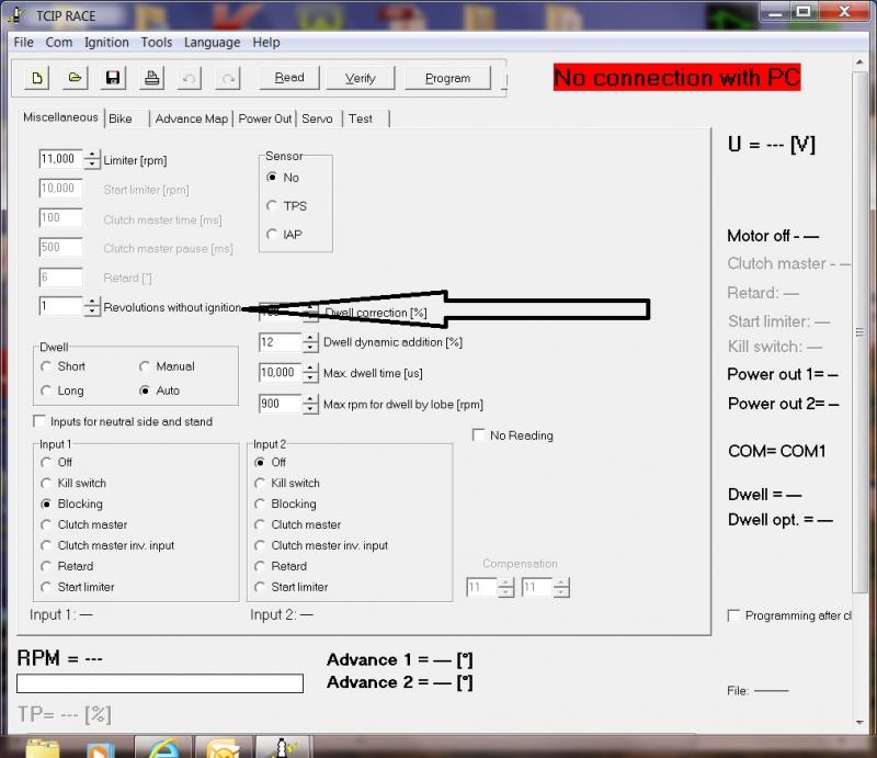
My first thought is that you accidently made a change to the "revs without ignition" setting on igntek software. Other than that I would suspect a problem with the ignition pickups
-
83 venture wont start
bkuhr replied to MILES MACK's topic in Venture and Venture Royale Tech Talk ('83 - '93)
If it started last weekend but not now I would make sure emergency stop on right handlebar is on. The ignition box on this is known to get moisture in it and cause problems, and need diode replacement. Am aftermarket ignition is 200-250. There are no points. Pickup coils under left cover and flywheel. If you want to get involved there are test procedures. Keep in mind this bike is 30+ years old, has not been taken care of, and will have issues. If you are capable to work thru the issues, you could end up with a sweet ride. I got my '83 for $300, buy it took most of a year and about $2000 to get it fairy decent. -
Auto cancelling turn signals?
bkuhr replied to oconeedan's topic in Royal Star Venture Tech Talk ('99 - '13)
You did not specify what year bike. The 83VR manual states 10 seconds or 150 meters (490 feet), whichever is GREATER. It works by starting a timer and pulse counter when turn is first turned on. Using reed switch on speedometer for counter signal. If turn on flasher and go, 140m counter will run out first, and 10 seconds will be last limit to determine time flasher is on. If turn on and you stop(at light), 10 sec will run out first, and flasher will remain on until 150m traveled. The 83 has a separate special timer relay/flasher. I modified mine here. http://www.venturerider.org/forum/showthread.php?63802-Here-is-my-modified-turn-signal-flasher 84 up has the special timer relay circuit built into the 41R starter cutout relay assembly -
I usually find when a high load worked for just a second and quits, then nothing works, even low loads- then the issue is at the battery connections. Typically take the connections apart, find and clean corrosion, and put back together, low lows will work again. Then you can determine if you still have issue with high loads such as cranking.
-
Just saw this- http://www.tapplastics.com/product/plastics/cut_to_size_plastic/acrylic_sheets_p99_non_glare_clear/514 Not adhering vinyl sheet, actually a acrylic plastic sheet, thinnest .080", but could possibly be made to work. Included video seems pretty good for antiglare
-
Got it running, but,won't move!
bkuhr replied to mandalore16's topic in Venture and Venture Royale Tech Talk ('83 - '93)
I think I would start by taking the clutch pack apart, verifying proper assembly and condition. Also I would clean with solvent the friction and steel discs, and drain the engine oil. This bike has a wet clutch, soaked in engine oil, and if the wrong type of oil had been added, the clutch plates will not grip each other. While the discs are out, with transmission in gear, rotate rear wheel to ensure clutch hub rotates, verifying nothing is wrong with the driveshaft/rear end. On reassembly soak the discs in the proper oil during assembly, and refill the engine when done. Use a diagram for proper reassembly, easy to get some parts in the wrong order, such as the splined washer! -
This is a funding campaign thru kickstarter.com for the creaters of a KIKO 3D printer, expected to be delivered 11/2015 If you are willing to risk $179, you could own your own personnel 3D printer to play and learn with. I think it would be pretty cool to be able to try 3D printing at home!
-
Side stand switch has 3 wires. One is ground, and when side stand is up, ground is applied to both other wires. One of the other wires, green/blue, controls the side stand indicator on the CMU. The 3rd wire, Blue/yellow, energizes the side stand relay coil. The contacts of the side stand relay, when closed, apply a ground to the TCI ignition unit for the unit to operate. Typically when a side stand issue arises, advise is given to splice all 3 side stand wires together, with the understanding that there is danger of travel with side stand down. You could also have a defective relay (contacts welded closed), or someone has done something to the wiring to bypass the system.
-
Probably not looking for an empty connector. Likely PO cut the 2 wires from the old side stand switch and spliced them together with some kind of connector or tape. This would have you looking for a plugged in connector with 2 wires connected together. Also possible the connector was completely cut off, and you are looking for 2 wires spliced together. Wire colors are blue/white stripe, and black. Should be tucked up fairly close to switch area. Maybe someone can post a pic of RSV side stand switch connector
-
snoops says FAKE snopes.com: All Motorcycle Owners Are Listed as Gang Members in the FBI
-
Company CARBON3D. Grows 3D items from UV curable resin, able to use the entire polymer family, from plastic to rubber. http://carbon3d.com/
-
Diode has continuity in both directions?
bkuhr replied to Vonwolf's topic in Venture and Venture Royale Tech Talk ('83 - '93)
Both diodes are used in the safety logic to prevent starter operation in gear or side stand down. They prevent backfeed to the safety relays(sidestand and start cutout). Both are wired in series to relay coils, so if you test in circuit, it would be possible to read continuity in both directions. Best to remove the diodes from the circuit and test again. -
You may not like this, but at our work, our IT department started a new security program that only allows specified, pre approved, usb items to be attached to company computers. The program they installed actually looked at the usb serial number, and if not on approved list blocks all data transfer, read or write. This applies to thumb drives, but also to other devices, such as camera's and usb hard drives, and different kinds of dongles. We had a time for a while getting IT to approve all our items. If wife's computer has similar security, only option may be to get official approval from her IT department.
-
LED wiring issues
bkuhr replied to dna9656's topic in Venture and Venture Royale Tech Talk ('83 - '93)
Just gotta ask, with all the bulb swapping. You have not by accident stuck a 1156 bulb in a 1157 socket. If so this could cause your cross voltage issue -
LED wiring issues
bkuhr replied to dna9656's topic in Venture and Venture Royale Tech Talk ('83 - '93)
Ok, sorry mis-understood issue just running lights side of 1157 led bulbs All I can think of is maybe a mis-alignment of the contacts on the bottom of the bulbs with the contacts in the sockets. Are all the LED bulbs you have from the same manufacturer? Have you electrically tested both contacts on the bulb actually light? -
LED wiring issues
bkuhr replied to dna9656's topic in Venture and Venture Royale Tech Talk ('83 - '93)
What are the specs of the resistor you are using, and is it actually hooked up to the circuit? If it is it should get warm to hot when turn circuit is on. I suspect your resistance is too high, not providing enough amp load for the flasher to work correctly. -
General Consulting, not motorcycle related. Car related
bkuhr replied to calperin's topic in Watering Hole
My thought is a new engine, and you know what you have, but you are likely to start to have other issues, next transmission, electrical.... Another unknown vehicle with high mileage will also be in the same boat, and need another engine and other parts soon Also suggest to check out vehicle pricing sites such as KBB or Edmonds. A quick look not knowing specifics shows 07 Saturn Aura worth about $3000. Could also check around for cost to repair existing engine, likely less than replacement unless valve/head damage -
LED Flasher Part Number/source
bkuhr replied to dna9656's topic in Venture and Venture Royale Tech Talk ('83 - '93)
The 83 does use a stand alone 3 pin flasher, and 2 pin hazard relays. both are behind the left front turn signal. I was able to modify a LED rated flasher to keep the auto-cancel function working http://www.venturerider.org/forum/watering-hole/63802-modified-signal-flasher.html The 84 and up has the flasher combined in the 41R cutout/start relay assembly behind the headlight -
Not to bad, but down release works backwards from what it should. A light press on the pedal is down FAST! A full hard press(is supposed to be slow) but its already down! Not to bad if you are ready for it, ...