
Search the Community
Showing results for tags 'wire'.
-
Sorry guys I tried the search first but it didn't come up with anything. Where can I get a wire to go from my Ipod to the bike? besides where, what would I be looking for?
-
I just installed the big horn from howards horns on my 06 RSV and it is VERY loud and great quality. I have never heard the stebel and others but my son has and says this is much louder. They actually don't give a decibel range for the horn. I used the hardware that came with the horn but they did not supply any wire...it is expensive at 150 bucks but worth the attention it attracts when I need it. After taking the stock horn off the right side, I used one of the existing holes from the stock horn mount, and used the black bracket supplied with the horn...I did not want to see any hint of a compressor so I drilled a 1/2" hole out the front of my saddlebag and mounted the compressor in the bag...a nice clean look, just a nice steel braided hose and horn showing to the rest of the world. They sent me wiring instructions for a Harley of course and wiring it that way to the relay did not work...so I found a thread on here about wiring another brand horn and it worked...just make sure the brown wire from the stock horn goes to post 86 on the relay, and the pink wire from the stock horn goes to post 85 and it will work using the existing horn button. They have several horns available but I wanted to make the most noise I can so went with the big horn.
-
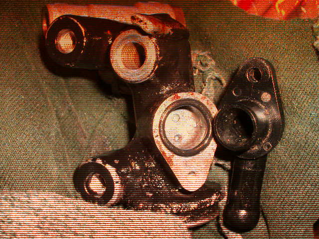
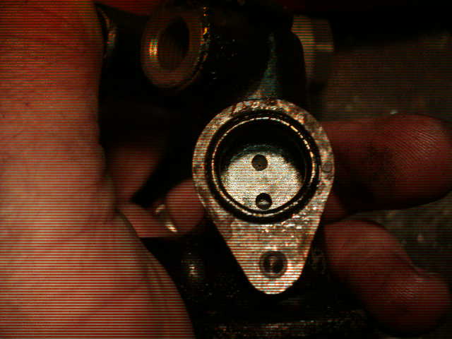
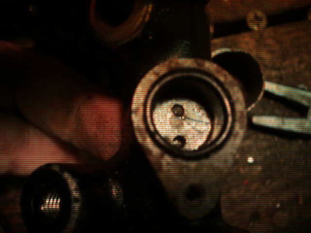
 Okay, if your on the road and your brakes stick on what do you do? I just finished solving this on my 1st Gen (83) and this may help you!! I am going to try and include pics with this!! I replaced my pads for a 10 day cross country ride coming up and ended up with a sticky Rear/front brake system.. If something like this happens to you here are some suggestions.. 1. If your bike feels like its lost power, is hard to push back and forth or if you just plain smell hot brakes - STOP and check them! 2. With a damp fingertip (spit works great) carefully touch the surface of your rotors (like testing a hot clothes iron). 3. If both left front and rear rotors are hot - its the rear system. If its just the right front its the front brake.. I am only dealing with the rear system at this time.. 4. If its the rear system, take an 8mm box end or a socket and open the bleeder on the front left caliper - have a rag hany cause if it is a stuck system your gonna get fluid out and you dont want it on your rotor.. 5. Push the bike back and forth or put it up on the center stand and see if the she rolls easy now.. If it does and the problem had effected both front and rear brake rotors (remember - your back brake pedal is activating both front left and rear calipers) check these items.. 6. Look at your master cylinder - at the bottom of it is a rod sticking out and an attachent for the pedal. Gently hold that rod between your thumb and finger and see if it has movement back and forth and a small amount up and down.. If it doesnt, you may need to clean the pivot for you pedal and/or adjust the freeplay screw to get play in it.. Now try your brakes - if still stickin go on to 7. 7. Pump your pedal HARD!! ALthough it is BEST to remove the rear brake master cylinder to do the following, so you can take it all apart and clean it thouroughly, I am going to give you some info for "on the road" fixen!! It also may be worth just doing this first BEFORE doing a complete take down - always start with lesser surgery first - I learned that from my NeuroSurgeon! 8. Expose the rear master. 9. Notice where the hose from the Fluid Resivore attaches to the Master. It is attached with a small phillips screw. Remove this screw. 10. Take a pair of pliers and squeeze the rubber line about 3/8th inch above the little plasic elbow that you just removed the screw from.. ITs best to have an extra set of hands there to do this as youwill want this line held closed during surgery. 11. Gently turn the hose back and forth to move the plastic "L" in its holder. Pull out while doing so.. The "L" is held in by an O-ring. 12. Make sure you dont loose the O-Ring when the L coomes out of the master - maintain squeeze on the hose (by the way, I carry a small set of surgical forcept pliers in my tool kit - VERY handy for all kinds of this stuff!) 13. Look at the pics I have attached - If you look closely you can see the little wire I have protruding from the return bleed hole back into the fluid res hose. This little hole is the hole that is on top of the cup that recieves the "L". 14. You WILL need a small wire to unplug this hole. I am using a bristle off a wire brush - someone who responded to my original thread about all this suggested this and it works GREAT!! I also use wire brush bristles for carb jet cleaning!! On the road I wouldnt be afraid to take a strand of wire from piece of wire (ya'll carry a little spool or wiring in your bag dont cha?).. 15. Push the wire into the top orfice and be prepared to get a SQUIRT! WHen I did this on my 83 it SQUIRTED out like a high pressure squirtgun!! 16. Work the wire in and out to clean out the orfice real good. 17. Wipe the insideof the cup where the L goes out real good. 18. Clean the surface of the "L" and the o-ring real good. 19. Relax the squeeze onthe hose and let a little fluid out. FLuid should RUSH out!! 20. If the fluid barely trickles. 21. Squeeze the hose again, point the opening of the L that goes into the Master down toward the ground. 22. Squeeze the hose above the pliers with your fingers. 23. Let go of the pliers a little so the fluid is forced out - you may be shocked what you get out of the hose - I WAS!! Re-Squeeze with the pliers as soon as it bleeds a shot!! 24. Replace the end of the L into the cup on the Master. 25. Release the pliers and squeeze the hose so fluid is gushing out around the L while pushing it in. 26. Replace the phillips screw!! 27. Pump your brakes and they should release and the wheels roll free. 28.. Put her back together and RIDE!!!!!!!!!!!! Oh yea, you might want to check your Brake Fluid first chance you get!! Special thanks to ALL who responded to my other thread about this!! Lots of GREAT info there folks!! "puc
-
 For a while now have had a skip at very light throttle, such as running at 40 mph on flat ground in 5th gear. And, as soon as I gave it any throttle, the skip went away. I have been thru the carbs, cleaned the pilot jets, synced them and replaced the plugs. This past week, I replaced the carb rubber manifold boots the carbs set on. Mine did have some obvious external cracks and the ones I used came off an 86 engine that I have and they look very good. Did not help a bit, ran exactly the same way. Yesterday morning I decided to remove all the YICS hoses and plug them. The two outer ones are easy to get off, but the two inner ones are hard to get to. I pulled one lose with a long pair of needle nose pliers, but on the other one, when I pulled it with the pliers, it tore into. This would have been easy with the carbs off, but I have already had the carbs off several times and I am tired of doing that. After I got the plugs on tight, I decided to replace the spark plugs again as I wanted to start fresh and to be able to try to get a reading on what the plugs looked like anyway. My son suggested I try the bike before I did anything else, but I did not want to get the engine hot. Well, when I pulled the back left cap off the plug, it came off the wire. Now these wires and caps were replaced a couple of years ago, so I did not expect them to be a problem. When I looked into the cap where the wire goes, there was green corrosion on the screw that screws into the wire. I cleaned it good and cut about a half inch off the wire and screwed it back together as far as it would go. It looked like the cap had not been screwed in good. I checked the other three caps and they looked good. I double checked the sync on the carbs and they were off some, so I adjusted them. I took the bike for a ride and it is running very good with no off idle skip. I am not sure whether the plugging of the YICS system was the problem or the cap problem, but at least it is running good again. RandyA
 -
1984 yamaha venture royal wire harness, fit an 1983 venture Dale
-
Conversion to Single Antenna Thanks to Steve Bumgardner (Bummer) While removing the gas tank I managed to lean in too far and snap the center load on the CB antenna. Guess I should have put it up while I was working on the bike. Live and learn. Problems: The stock antenna is $140 or so, and it's obviously not very stout. The twin antenna system reduces the efficiency of the CB antenna. Probably not enough to worry about, but it's there if you like to sweat that sort of thing. Solution: One antenna serving both radios. Note: Some splitters reduce output power. Testing indicates that the Firestik splitter does not reduce final output power to the antenna. 4 watts in, 4 watts out. Many thanks to Marshall Gammon for his site http://bludolphintravel.com/gmg/marshallmod.htm It was a wonderful starting point. Preparation: Read the manual with the splitter. Read and understand the manual that came with your SWR meter. Check out the help files on the Firestik site http://www.firestik.com/Tech_Docs.htm If you've never worked with coax you should probably read http://www.firestik.com/Tech_Docs/Coax_Procg.htm for tips. Parts: 1 Firestik Firefly 3 foot CB antenna $18.00 http://www.walcottcb.com/product_info.php?cPath=28_97&products_id=897 1 300-340 stud mount base $5.00 http://www.walcottcb.com/product_info.php?products_id=251 1 folding mount $15.00 – This part is way too sloppy but it works if you require a folder. http://www.walcottcb.com/product_info.php?cPath=29_112&products_id=262 1 90 degree PL-259 adapter $5.00 http://www.walcottcb.com/360359-coax-right-angle-adapter-p-233.html 1 CB FM splitter $18.00 http://www.walcottcb.com/product_info.php?products_id=221 1 PL-259 male plug $2.50 1 PL-259 reducer model UG176 $.50 http://www.radioshack.com/product/index.jsp?productId=2103401 1 Motorola female $1.50 2 Motorola male $2.00 Solder and shrink tubing Installation: The CB lives in a plastic box under the trunk. The lid is held in place with two rubber straps. This mod assumes access to the CB by removal of the trunk as needed. (Remove six screws in the bottom of the trunk, then close the trunk and carefully rotate the rear up and forward. There's wiring up front. I used the 'balance with forehead' technique to hold it up whenever I needed to get to the CB. The red spot's almost gone. Be careful. It's way too easy to put a nasty scratch in the trunk while you're doing this. Sigh.) Remove and do as you will with the old antenna. Mine may eventually grow up to be a flag mast. Remove and retain the wire between the antenna and the CB. Place the stud mount base on the antenna support with the nylon washer at the top. If you are using one place the folding mount in the stud mount, with the fold pointed front/back. Screw the antenna into this. Don't get carried away with the antenna itself. All else should be tight. Screw the 90 adapter into the bottom and aim it toward the radio. http://www.venturerider.org/antenna/image002.jpg Antenna base. I had to use a file and cut two notches in the stud base. Most PL-259 females have notches all around so that the locking points on the male can keep it from rotating while maintaining good contact. This one had none. A half dozen swipes with an edge of a triangular file did the job. http://www.venturerider.org/antenna/image004.jpg The notch Use the old wire to measure where to cut the CB Antenna Out wire on the splitter. Solder a PL-259 male plug on the wire you cut off. This is your new antenna wire. Put a male motorola plug on the CB Antenna Out wire of the splitter. http://www.venturerider.org/antenna/image006.jpg Wiring details. http://www.venturerider.org/antenna/image008.jpg Finished wiring – I didn't shorten the FM antenna wire the first time. It doesn't have to be, but it makes the box a bit crowded. Screw your new antenna wire into the 90 at the base of the antenna. Test for continuity and shorts. The tip of the antenna should have continuity with the center of the CB antenna wire. It should not have continuity with the outside of the plug. The CB antenna wire shield (outside of plug) should have continuity with the antenna support that came with the bike. Screw the end of the antenna wire into the splitter's Antenna In plug. Route this wire through the hole the old antenna wire went through. Plug the CB out wire into the CB box (gray plug). Remove the FM antenna, base and all. Cut the end off of the FM wire and solder the female Motorola plug on. The core goes to the center of the plug. The shielding goes to the body of the plug. Use some shrink wrap to cover the whole thing. Cut a notch in the side of the plastic box and route the FM antenna wire with the new plug into the box. I made a notch in the lip of the top and a matching one in the slot of the box. I kept this a tight fit to keep water out. Plug the splitter's FM Out lead into the FM antenna wire, fold it up into the box beside the CB. Place the splitter under the wires coming into the box on the left. Massage all the wiring to fit. Close it up. http://www.venturerider.org/antenna/image010.jpg In the box. Now that everything fits, it's time to set the Standing Wave. THIS MUST BE DONE or you'll toast your CB output transistor. Remove the plug from Antenna In on the splitter. Remove the plug between the splitter and the CB. Add a male PL-259 to male motorola patch cord to the antenna input wire (gray plug). Let the patch cord and the antenna wire dangle outside the box. Put the trunk back in place. Plug the antenna wire into Antenna on the SWR meter. Plug the wire from the radio into Radio on the SWR meter. Set the standing wave as per meter instructions. I got a meter at the Rat Shack. I got a http://www.walcottcb.com/product_info.php?products_id=934 and a http://www.walcottcb.com/12mfpl-pl259-to-motorola-female-12-long-p-198.html to connect the meter to the antenna system. I had to screw the adjuster on the antenna most of the way in. After some tinkering with the tip I got a 1.3 on 20 and just under 1.7 on 1 and 40. Once the antenna SWR is set you have to tune the splitter. Connect the antenna to Antenna In on the splitter. Connect a male motorola to male PL-259 patch cord to CB Out on the splitter. Connect these to your meter and check SWR. You'll have to turn the CB adjusting screw on the splitter to bring the SWR back down to where it was when you set the antenna. Mine is turned all the way down. You can now set the AM as per splitter instructions. When the antenna and splitter are both set disconnect the meter and the patch cord. Put the antenna wire back on Antenna In and the CB out wire into the gray socket. Pack everything back into the box, put the lid on, and bolt the trunk back in place. Breaker, breaker, two nine. End result: Single antenna system for under $75.
-
Sending Unit Repair Thanks to Brian H. (6m459) for this excellent article. I measured my sender unit resistance and found it to be open circuit as was suggested by another member. I removed it from the tank to find that the wiper would loose contact with the resistance wire at the mid point, of the float travel, as the resistance wire substrate is warped. It made good contact at top and bottom but not in the middle. I found that there is a handy adjustment available that lets you re-tension the wiper quite easily. Undo the screw and slide the bushing closer to the resistance wire, against a compression leaf spring, then re-tighten the screw. All seems to work well again now but I'll be keeping a close eye on it for the next little while. Shown with cover removed. Note bend in resistor wire substrate. http://www.venturerider.org/sendingunit/1%20(Small).jpg The wire loses contact with the resistor midway. http://www.venturerider.org/sendingunit/2%20(Small).jpg Solution: Loosen screw, slide wiper closer, retighten. http://www.venturerider.org/sendingunit/3%20(Small).jpg Close up view. http://www.venturerider.org/sendingunit/4%20(Small).jpg
-
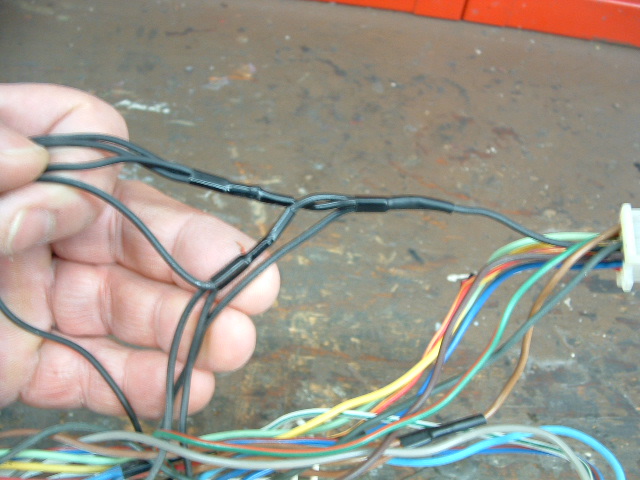
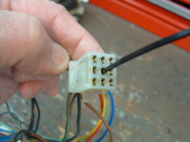
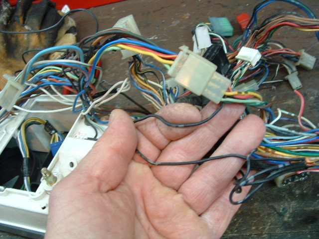
Over time I have heard many folks talk of Instrument panel lights going out or going Dim . And Tachometer not working at same time. Some say the Side Stand switch has something to do with it. I'm trying to track this down on the schematic, but have not figured that out as yet. The Schematic, only shows, Ground Symbols for the light sockets, and does not show where the ground connections are actually made to the frame of the bike or in the wireing harness. I decided to dig into this, and find the Actual ground connections. I have a junk Inst Panel, and Wireing Harness I use for parts. Here is what I found . 1. On the Instrument Panel, there are ( 8 ) black ground wires, comeing from the various light bulb sockets . They are all connected together thru a series of three splices, and then one wire goes to Pin 5 of the Nine Pin White connector ( the female plug ) located 8 inches to the left of top center of the instrument panel ( your right looking thru head light area ) 2. The black wire comeing from pin 5 then runs into the wireing harness. I opened up the Old harness, and followed this wire, it goes thru "" Three""" more Crimped, and taped splices, and eventually gets to a ground stud, near the left side of the battery. 3. If you are missing a ground to the light bulbs, ( On the Inst Panel ) or have a High Resitance ground to them, what would be AN EASY AND FAST FIX ????? See, my photo, showing the Black wire from pin 5 of the "Male" side of the plug. The wire in question laying across palm of my hand. Seems to me, you could Cut, the wire here, and splice in a chunk of about # 16 or #18 stranded wire, and run this wire to a Convient Ground point somplace in the forward fairing area. This would insure that all the bulbs in the Panel Now have a good ground. Also, just pulling this connector apart, and useing some contact cleaner on it would be a good place to start. I am open to any and all comments, or corrections. GeorgeS
-
I have a set of six coils off a Nissan Maxima engine that have the coils right on top of the sparkplug boot. I was wondering that if they would fit on top of the plugs on my bike, could I bypass the coils I have and run the respective wire that goes to the coil to the spark plug coil. I believe they only require a hot wire and a ground wire. Has anyone done this? I don't see why it would not work if the room in the plug area is suffient. Any comments? RandyA
-
I've read this so many times I can't see it any more. Typos and questions: I'll be glad to correct/explain as needed. How to make your passing lamps modulate when the horn is activated. If they are not already on they will be turned on while the horn is activated. Some information: Headlight modulation is authorized throughout the US by the DOT. It is wise to carry a copy of the law in case you find a LEO who doesn't know this. You can't legally modulate at night, and all modulation must be synchronized unless you're a LEO. Most Diamond Star modules have a Heads Up mode. This causes the attached lights to flash for three seconds when the horn is honked. I wanted my passing lamps to flash as long as I hold down the horn button. As I was finishing this up (I thought.) I did a final check for parts availability. It turns out Signal Dynamics has changed models and the newest one won't work. Some old Diamond Stars might be available, but I'd definitely call and check the number. Because of this I added the instructions for Kisan modules as well. I have not used the Kisans myself. (See Notes 3 and 4 at the bottom for more info.) Schematics follow at the end of the article. 1 – Using a relay to activate the passing lamps. Lamps installed as per Yamaha instructions. 1 normally open horn relay Wire Female lugs Wire loom material Fuse (inline or mini addon fuse block) Remove seat and tank. Split fairing. Run a wire in wire loom from the battery, up the backbone, through the neck, and into the fairing. Use an inline mini fuse or an addon fuse block. Depending on how much of this mod you want to do you may want to run more than one wire. This is a power wire – 12 or 14 gage. This wire goes to 30 on the relay. Find the wire that's patched into the red/yellow high beam wire. Cut this wire between the switch and the passing lights. Place a female lug on the wire that goes to the headlights and put it on 87 on the relay. Place a female lug on the wire that comes from the switch and put it on 85. Run 86 to ground. If you don't care about the modulation and horns you can use some double stick tape, stick the relay to the bulkhead, and stop here. You'll have your passing light powered from the battery, activated by a relay switched only when the power is on. You've also reduced the load on your headlight circuit. 2 – Add a horn activated modulator. 1 Diamond Star modulator #01014 (Follow DS instructions – red to power, red and white to light.) OR 1 Kisan pathBlazer P115W–H3-HD (Follow K - instructions.) 2 horn relays Wire 2 Piggy back lugs (Radio Shack Quick Disconnect Adapter Set 64-3064) Some female lugs Wire loom material. Double stick tape Remove left lower. Remove tank. Loosen/remove neck plastic. Split fairing. Run two signal wires (16 or 18 gage) in wire loom up from the area of the horn, through the neck, and into the fairing. If you are retaining the stock horn, solder/crimp piggyback lugs to the wires and place on horn. Place plug on piggyback. If you're removing the stock horns use standard male lugs. Put the lugs into the horn plug. Toss the horn. http://s_bumgardner.home.comcast.net/lowerfairing.jpg (horn area of lower) From the front of the bike run the horn signal wires to your right. Give yourself a foot of wire or so to work with and trim, then add a female lug to each wire. In order to keep some of the wiring under control I made a harness for the relay set. I used double stick tape to stick the relays together side by side, then placed lugs on each 85 and 86. I routed the wires that go to the front connectors toward the back next to the other wire. Once everything was in place I crimped the lugs onto the wires, and wrapped the wire sets with electrical tape in strategic spots. I put male lugs on the ends of the two wires. http://s_bumgardner.home.comcast.net/relays.jpg (Relays and wiring harness) Plug the two male lugs from the relay harness into the females on the horn signal wires. First relay – doesn't matter which. DS - Cut the toggle switch off of the modulator, leaving the wire. Solder a female lug to each wire. Hook these to 30 and 87a. K – Cut the red wire on the light sensor wire set and splice in enough signal wire to reach the relay. Solder a female lug to each new wire. Hook these to 30 and 87. Cut your passing lamp power wire between its switching device (switch or relay) and the lamps. Install the Diamond Star or pathBlazer module on this wire as per its instructions. Decision time: Do you want the lights to flash at night? Technically this is probably illegal. The main headlight may not modulate after dark. Period. These however are passing/auxiliary lamps flashing when you honk the horn. Their use presupposes an emergency wherein I want the clown about to run me over to notice I'm there and change his mind. I don't care how the DOT feels about it. If you decide to have them flash at night you need to: DS - cut the sensor off, then solder the wires together and insulate the end, then tape it out of the way. K - mount the sensor where it receives light from the headlight. The pathBlazer uses an adjustable sensor, so cutting it off probably won't work. If you want the light to not flash at night follow the standard sensor mounting instructions for each. I mounted the one for my headlight in the plastic piece at the bottom of the fork, toward the back, pointing down. There's room for two. I removed the sensor for the passing lamp modulator. http://s_bumgardner.home.comcast.net/lightsensor.jpg (Sensor placement) Pick a second relay. Splice into the light power wire before the existing switch/relay. Run this wire to 30. Splice into the light power wire after the existing switch/relay and run this wire to 87. http://s_bumgardner.home.comcast.net/relayswired.jpg (Relays - from left: Horn - Headlight modulation - Passing light modulation - Passing light power with horn. Separate - Switched passing lamp power for normal operation.) Use double sided tape to stick the relays and modulators to the bulkhead. If you're doing the horn and/or headlight modulator, save this step for later. http://s_bumgardner.home.comcast.net/relaysinplace.jpg (Relays in place on front right, lower bulkhead) You can stop here, your passing lamps will now flash when you honk the horn. If they are not turned on, the second relay will turn them on while the horn is activated. Power on, test, and button up. 3 - You can add a set of Fiamm Extra Loud electric horns inside the fairing. Just add another relay in parallel with the others (85 and 86), then use this to power the horns. The Fiamms will fit inside the fairing. The supplied mounting brackets must be attached to the radio mounting bracket, one on each side. The brackets must be massaged to get the horns to fit without touching the fairing. I used two of the mounting brackets on each horn to get good strength. One seemed too weak. You may find that the upper bolts yield a better position than the lower bolts. Run a fused wire from the battery to 30 on its relay, then from 87 to both horns. Ground the horns to the radio framework. http://s_bumgardner.home.comcast.net/horns.jpg (Fiamm horns) Parts for this: 1 set of Fiamm Extra Loud electric horns (132 db) 1 horn relay A couple more lugs A bit more wire 4 - You can also add a headlight modulator on the high beam. If you do, add another relay to the horn circuit, same as above. You will need to turn off the headlight modulator when the passing lamps are modulating. DS - Cut the toggle switch off the headlight modulator and add lugs. Put these on 30 and 87. It'll turn off the headlight modulator while the passing lamps are flashing. K – Cut the red wire to the light sensor and add two wires with female lugs on the ends. Route these to 30 and 87a. This will turn off the headlight modulator while the passing lamps are flashing. Parts for that: A Diamond Star module installed to the high beam as per instructions (red to power source, red and white to light). OR A pathBlazer P115W–H3-HD module installed to the high beam as per instructions. 1 horn relay A couple more lugs A little more wire If you didn't stick it all to the bulkhead earlier, now's the time. Power up, test, and button everything up. Note 1: I went to Pep Boys, in the horn department, and found good quality relays for three bucks each. They have both normally open and normally closed terminals. I've found low end relays with 87a cut off. These will work for all but one place on the Diamond Star install. The relays used on lighting systems cost five bucks each and all require a fancy harness and plug to remain fully rigid. Used without the plug these relays can be activated by moving the wires attached to the switch lugs. Note 2: If you get the Fiamms from this place, you'll get a five lug relay and all the rest of the stuff you need to add the horns. Note 3: Any Kisan pathBlazer will probably work for the main headlight. All you need to be able to do is interrupt the signal from the light sensor. I contacted Kisan and a tech there verified that opening the sensor circuit would cause the modulator to return the light to solid operation. That's what we want. Note 4: Newer Diamond Star modulators (#01013) will not work. If it hooks up to a single light and has a switch, and/or light sensor, it should work. Bear in mind that the Diamond Star module # 01014 modulates when the switch is OFF and stays on solid when the switch is ON. The Kisans modulate when ON and stay on solid when OFF. In other words, if it flashes at the wrong time move 87/87a to the other. (Schematics) http://s_bumgardner.home.comcast.net/circuitDScolorFinal.jpg (Diamond Star #01014) http://s_bumgardner.home.comcast.net/circuitKisanColorFinal.jpg (Kisan pathBlazer)
-
 …from past threads seams to be missing some details and I hope some of those past contributors (or anyone) can fill in some gaps for me. Here is the scenario I was thinking of: Fieldsheer Air-Tex mesh jacket with zip-out “water-resistant/thermal liner” (on-hand). 30-40 feet of 30 AWG multistranded Teflon coated wire ($4) WarmGear Heat-Troller Single Portable Temp-Controller WG-SPCOAX ($70) WarmGear SAE to Coax Jack (Female) WG-DCJK150SAE ($5) In theory, I could plug the SAE-to-coax adapter to the existing SAE jack that came already attached to my battery, then plug the heat-troller coax to the coax adapter (in lieu of using the battery harness that comes with the heat-troller), and plug the jacket coax into the other heat troller coax. (right?) …but naturally I would have to wire the jacket liner in such a way as to end up at a coax connector. This is where I am lacking information. I assume I would turn the liner inside out (?) and lay out the 30 gage Teflon wire back and forth around the jacket and hitch it down so it will stay put. I further assume I would leave a pigtail of wire near the waist/bottom for attaching to the coax jack. What I don’t understand is how to attach the 30 AWG (isn’t this a single wire?) to a coax jack. I thought I read somewhere that the 30 gage wire has to be upsized into an 18 AWG wire (if so, what kind of wire is this [two-wire?]? I.e. red/black zip cord from bulkwire.com? how is this connection accomplished?) and then the 18 AWG is attached to the coax jack (how is this accomplished? Where can I find a coax jack to match?). I’ve seen all the comments about just buying a heated vest, but dang they’re expensive. This looks like a project I could spend the summer doing since I won’t need the liner in the jacket. I’m pretty good with a variety of hand and power tools and a civil engineer by education (but by definition merely dangerous in the electronics department). Bottom Line: I don’t quite understand how to make the wiring connections for a DIY heated jacket. Hope someone can help. Thanks. David
 -
I'm installing a Sirius radio and want to wire directly into the ignition switch so power goes on and off with switch. Theres 4 colors and I don't have a tester handy. Anybody know? It's a 2005 RSTD. Thanks. Mike
-
 Modulite Installation Note: The Modulite and similar units are designed for isolating and converting your trailer wiring from the bikes lighting circuit. These units are designed to go from a bikes lighting system which uses separate turn signals to a conventional trailer lighting setup that combines the turn signals with the brake/tail lights. It will NOT work if your trailer uses conventional motorcycle type lighting with separate turn signals. If your trailer uses motorcycle type lighting, you will need to purchase an "isolation" unit. There are several on the market. Bushtec sells their own unit and the Electrical Connection also sells one. Here is a link to the unit at the Electrical Connection. http://electricalconnection.com/wire-harnesses/hrns-trailer.htm This installation is for the Modulite trailer wiring kit. The specific one that I used is model 18146. There is more information on this unit HERE. There are other models and brands that will also work but this just happens to be the one that I used. There are a number of places that this unit could be mounted and other ways that the wiring can be routed to the plug at the rear of your bike. This way worked well for me. This installation is on the Yamaha RSV but these units will also work great on the First Gen Venture or the RSTD. I mounted the unit under the seat. This particular model is slender and will slide down beside the battery. Here is a picture of the unit. http://www.venturerider.org/modulite/moduliteout.JPG Wiring is fairly simple. Anybody can do this job if you simply follow the instructions and take your time. There are 6 wires coming out of the unit from the side that says "To Car"...or in our case..."To Bike". There is a black wire that is labeled 12V...you need to run that wire through an inline fuse and then directly to the positive battery terminal. There is also a "ground" or "negative" wire that will connect to the negative terminal of the battery. There are 4 wires that connect to the wiring harness of your bike. An easy place to splice these into the bikes harness is at the natural color connector just behind the battery. http://www.venturerider.org/modulite/connections.jpg You can see that I used snap type wire splices for this but I plan to redo these over the winter and use soldered connections. I am just not a big fan of these snap splices. They will work though if you don't wish to do the soldering. The connections are as follows. There is a green wire marked "right signal" out of the Modulite. Splice into green wire at bike's connector. Yellow wire marked "left signal" out of the Modulite. Splice into brown wire at bike's connector. Red wire marked "Stop" out of Modulite. Splice into yellow wire at bike's connector. Brown wired marked "Tail Lights" out of Modulite. Splice into Blue wire at bike's connector. That's it for the wiring. Now just tape up the splices you made. http://www.venturerider.org/modulite/connectionstaped.jpg These next two pictures show how I slid the unit into the space beside the battery. The first shows it about half way in and in the second picture, it is slid all the way down. I used a tie wrap to secure it there but it wouldn't go anywhere even without one. http://www.venturerider.org/modulite/modulitehalf.JPG http://www.venturerider.org/modulite/modulitein.JPG All that remains now is to run the wires coming out of the "To Trailer" side of the Modulite to the hitch of your bike. I ran mine across the top of the fender first and under the trunk. http://www.venturerider.org/modulite/fenderroute.jpg I then came out from under the trunk and through rubber grommet behind the license plate so that I could route the wires on the inside of the rear fender. As you can see...I also used some wiring loom to cover them at this point. http://www.venturerider.org/modulite/rearroute.jpg Finally, I brought them from inside the fender about the hitch and to the connector. As you can see, I again used some wire loom and also replaced the flat connector with the round type. That is simply a matter of choice. http://www.venturerider.org/modulite/hitch.jpg That is all there is to it. Pretty simple and works great.
 -
FAULTY IGNITION SWITCH Temporary Repair A few weeks back I stopped for gas, and when I turned the key on there was no electrical power, except for the radio. There was no lights on the dash, no headlights, or any other power, except for the radio. After checking all the fuses, which were okay, it was suggested the ignition switch could be the problem. To get to the ignition switch wires you will have to remove the seat and the top cover by the key (two Allen head bolts), and then remove the Fuel tank, by first removing the breather tube on the top of the tank, the electrical connection and the fuel line (under the tank). There are two Allen head bolts at the front on each side of the tank, and one bolt near the seat, before you can remove the Fuel tank. After removing the fuel tank there are two plastic covers on each side of the switch, which are held on by a small Phillips head screw and a plastic plug. http://www.venturerider.org/switch/image001.jpg Referring to the manual, Section 8 page 2 stated that switches could be tested for continuity. The manual states, on the main switch there should be continuity between the brown/blue wire and the red, and between the blue/yellow and blue/black wires, when the switch is turned on. I used a multi meter and started checking the wires for continuity. This should be done on the backside of the plug, to prevent damage to the plug connections. I found that I had continuity between the Blue/Yellow Wire and the Blue/Black Wires, however I did not have continuity on the Brown/Blue Wire and the Red wires. I used a 10-gauge wire and inserted it on the backside of the plug between the Brown/Blue Wire and the Red wires and then I had power on the dash and fuel pump started clicking. Therefore, I spliced the Red wire and the Brown/blue wires and connected a 10-gauge wire to the spliced ignition switch wires. I ran this new 10-gauge wire to the handlebars and connected these to a 50-amp single pole toggle switch, which I taped to the handlebars. Please note the 50-amp switch is most likely much larger than required. http://www.venturerider.org/switch/image003.jpg http://www.venturerider.org/switch/image005.jpg New Switch http://www.venturerider.org/switch/image007.jpg Wires (on new switch) http://www.venturerider.org/switch/image009.jpg When there is no continuity between the Brown/Blue wire and the red wire there will be no power, except for the radio. These wires close the circuit to the main fuse, battery, starter relay, starter motor, and the Start Switches (including the clutch, neutral, side stand, and stop switches).
-
Alright, so that '77 XS750 that I bought... I was tinkering with it this weekend and all said and done, I got the old girl to fire up. I traced my prior electrical issues to a faulty ground wire... specifically the one running from the battery to the ground on the engine. I'm thinking the connection at the battery is to blame, but as there isn't much slack in the wire unless I re-route it, I think I should just replace it.. so my first question: What guage wire should I use to replace the ground? And is that something that would generally be easy to get? Next question: Whoever owned this bike before me... I have no clue what this guy was thinking when he worked on it... but the airbox was in pieces, parts of it were missing... and there was no air filter. So I opted to remove the air box completely and go with the clamp on style pod filters. This left me with my new problem... the bike has a hose that ran from the back of the engine into the airbox... The shop manual states that this hose routes carbon emissions back through the carburators to be reburned. the original air box had a spot where this connected, but with the pod filters I'm stuck with leaving that hose hang loose. When I had it running, I was getting some nice smokey exhaust coming up out of this hose. Anyone got any ideas on what I can do with this? Should I just plug it or should I try to fabricate something to cycle it back into the carbs? Final question: once again, no clue what the previous owner was thinking, but the wires to all the lights (brakelight, headlight, turn signals) have the grounds all spliced together into one ground. And the guy evidently didn't know what to do with it, so he wrapped it in electrical tape and left it hanging loose. I jury-rigged a wire to it and connected it to ground and amazingly enough, all my lights that I thought were dead came to life! so now for the question: Do I just ground this to my battery or should I run a new wire down to the engine ground or just ground it to the frame? Thanks in advance for ya'lls help. I really appreciate it!
-
Has anyone else had this problem? The wire harness for the front turn signals, light bar, etc, is routed right between the steering stops below the headlight...In the past few weeks, a wire has worked up over the stop and been pinched and shorted out the lights. Last night I lost all my lights, I found the right turn signal wire cut and fried, last week it was one of the light bar passing lights, and before that , the same turn signal. I have tried pulling them as far as they will go in either direction, and still stay plugged in, but they keep working back in the line of the pinch point. I used zip ties to get them out of the way this time. I think I have an idea about an alternative way to route them but it may require drilling a hole in the back half of the fairing and feeding them through...this would eliminate the problem altogether... Unless someone has a better idea, I will try that next week... I am heading out for a few days this Friday for a color tour, so I don't want to tear into it right now....stocking up on fuses and electrical tape for the trip in the mean time...
-
LIGHTS LIGHTS AND MORE LIGHTS It seems that every time we buy some thing new for our venture it has a light or two attached or needs 12V power to run it, and the alternator can only give so much to keep up with our demands for more power. The alternator can produce between 20 and 24.5 amps and after taking away the 10-12 amps needed for the normal operation of the bike you have about 10 amps to work with. Now when you add a trailer you tax the system even more because most trailer lights take about 2.5 amps for running lights and 5-6 amps when the brake lights come on. That doesn't leave much left for the rest of the goodies we have installed that use power so it would seem we have a problem? NO PROBLEM, it only means we need a power manager and the simplest is to have all of the lights we have installed on one or more switches so we can turn them off when there not needed. Speaking of installing lights, trailer or a sidecar the following are some tips on the best place I have found to hook up to power. Lights For lights; any convenient brown wire will supply 12V switched on by the key, but if you also wish use a power bus to supply all of the extra lights you have added, then use the large brown wire coming from the Ignition. switch and be sure to add a 15-20A fuse because this wire comes directly from the main fuse through the Ignition. switch. Then use this source to power all of the switches to control your lights. Trailers Trailers are a different story because your brake lights and tail lights are monitored by the computer and if they are hocked up wrong they can damage the sensor board in the computer. the safest place to attach trailer lights is at the rear brake switch using the brown wire for the running lights and the yellow wire for stop lights. For turn signal lights you can connect directly to the dark green wire at the right turn light and the chocolate wire for the left turn light. For those of us that all ready have trailers and extra lights it might be a good idea to check on the wiring to see that it was done the safe way. Relays I have found all sorts of uses for relays on my Venture, the following is a setup I use on my 91. The relays are from Radio Shack and are for circuit board mounting, they will carry 10 Amps and only require 160 ma to operate the coil. The wiring is straight forward "NO" is the normally open contacts, Com its the wiper or moving contact, the coil has no polarity, #5 is Bat - Frame or black wire; #10 is bat + and I used a 15 amp fuse on this wire; and for the sake of the explanation I will give the rest of the wires a function, #1 wire is connected to the brake light and # 9 wire goes to the trailer stop lamps; # 2 wire is connected to the tail light and # 8 goes to the trailer running lights, #3 wire is connected to the right turn signal and # 7 wire goes to the trailer right turn light, # 4 wire is connected to the left turn signal and # 6 wire goes to the trailer left turn light. You my ask why go to the trouble to have a relay on the flashers; Well their are two reasons #1 when you connect your trailer flashers directly to the bike you load the system and the flashers go to fast, # 2 all of the lights on the trailer are brighter because their running on full voltage. Also if something shorts out on the trailer you don't loose a fuse on the bike. I used 18 ga wire on # 5 and # 10 and 20 ga wire on the rest. The computer monitor costs over $900.00 at a dealer. http://www.venturerider.org/pictures/4relay.gif Fred Vogt 1037
-
At the Large White Plug, with the 3 #14 wires comeing from the Alternator: Do the following: Measure the AC voltage on each wire. You can stick the meter probs into the end of the White Plug. ( located just behind left rear cylinder, White connector, with 3 white wires thru it ) With Engine running, you should Read 9 to 15 volts AC, ( thats AC, not DC ) on each wire. If the voltage on " one" wire is substantially , Lower then the other two, then your Alternator is failing. This is a much better way to check it then useing the Resistance reading method given in the Service Manual.
-
Fiamm Horn Installation You folks know very well that there are usually a number of ways to do a job. I'm not saying that this is the absolute best way of installing these horns but it's the way I did it. If you have suggestions on how to improve on this, please start a discussion in the General Tech area and maybe we can all learn something. That being said...this is my story. Though this installation was done on my second generation Venture, I'm sure that much of the wiring and etc. would apply to the first generation or the Royal Star also. I ordered the chrome horns with the intention of mounting them somewhere on the side of the bike. I just couldn't find a place that I like though so finally decided to just mount them inside the faring. Obviously I would probably not have bought chrome had I known that I was going to just hide them anyway. The first thing you have to do of course is split the faring. If you have never done that, I posted a separate write-up on my procedure for doing it under the Second Generation topic of the Technical Library. Once you are inside the faring, the rest is fairly straight forward. The particular horns came with some chrome straps about 3" long with a hole in each end. As you can see, I utilized holes that were already in the part of the faring frame that holds the speedometer unit. There are two holes there that are not being used. There are rubber pads in the holes but I just popped them out and put them away in case I ever need them. This is a steel frame and is very solid. These horns are actually self grounding through the mounting lug but the bracket that I bolted them to is painted so it was a matter of scraping off the paint or using a ground wire. I decided to use the ground wire. Why create a place for corrosion to start by scraping off the paint. I simply used a piece of #14 wire with ring terminals on both ends. Just under the audio unit on the right side is a ground wire and I just connected two new ones to the same screw...one going to each horn. Now...the horns came with a relay and if you are installing heavy duty horns, you certainly want to use a relay. As you can see, I simply removed one of the screw that holds the audio unit and bolted the relay right to it. Very simple. http://www.venturerider.org/horns/relay.jpg The white wire that you see going to the relay is the main power for the horns. The instructions say to simply run a wire to the battery through an inline fuse that you'll have to purchase elsewhere. There is nothing wrong with that but I didn't have an inline fuse and didn't want to go to the store. After thinking about it, I decided to power it off the same circuit that powers the 12V receptacle. Now if you use the receptacle for heated clothing or other heavy duty items, you will want to do as the instructions say and run a wire to the battery. In my case though, I only use the receptacle to power my IPOD MP3 player and it pulls hardly any amps at all. So...I simple ran the white wire from the relay across to the wire going to the receptacle and spliced it in. If you take this route, you WILL want to go to a bigger fuse on that circuit. The receptacle is fused for 5 amps and they horns call for 10. This fuse is located inside the lower left cowling as indicated by the next picture. http://www.venturerider.org/horns/fuses.jpg They are marked inside the lid of the fuse box so simply remove the 5 amp fuse and replace with a 10 amp. So... you now have main power to the relay and the horn is grounded. All you need to do now is connect the relay to your horn button. So...where the heck do you do that? Well....If you look carefully at the next picture, you will see where I tied into a pink wire. This is the wire that comes off the horn button. It did go into the plastic connector you see just below it but I simply pulled it out of the connector, cut the end off and crimpled it to my wire going to the relay. So now the horn button can trigger the relay and all is great. One note. I had intended to leave the original horns connected as well as the new ones. Due to the circuit feeding back through the original horns though, I found that the new horns would honk when the key was in the accessory position. Rather than mess with isolating them and due to the fact that you can't hear them anyway, I just decided to heck with them. Here are pictures of the left and right sides. http://www.venturerider.org/horns/left.jpg http://www.venturerider.org/horns/right.jpg My opinion of these horns? They are MUCH better than the stock horns. I can assure you that you will be heard when you set these things off. Even still though...I expected a bit more. I mean...if you run up behind somebody and press the horn button...they are going to JUMP...but..they probably won't wet their pants. I wanted them to wet their pants....maybe I expected too much. Anyway, if I had to rate them between 1 and 10...I would probably give them about a 7. If I had it to do over again...I would do so...but if I was putting them in the faring, I would just go with the round plain type...not these chrome models. Don Nelson
-
YAMAHA VENTURE BATTERY REPLACEMENT AND CM WARNING BYPASS BY JACK (Condor) CHALAIS http://www.venturerider.org/battery/YAMAHA%20AGM%20BATTERY_files/ODY1.jpgBecause we were experiencing hard starts, erratic cold starts, and low battery voltage after our '83VR sat for a few days, we decided to replace the existing battery, installed by the previous owner, with one of the new AGM (absorbed glass matt) batteries that have recently become available due to new technology. Having never had any experience with these new maintenance free types, but doing a lot of research we felt that a new ODYSSEY AGM would solve a lot of our hard start problems. For more info click here http://www.venturerider.org/battery/YAMAHA%20AGM%20BATTERY_files/ODY2.jpgAfter removing the false tank cover, the battery is located under fuse holder. Remove the fuse box by unhooking the rubber hold down strap.http://www.venturerider.org/battery/YAMAHA%20AGM%20BATTERY_files/ODY3.jpgWith the fuse holder out of the way the top of the battery with the low battery acid sensor. http://www.venturerider.org/battery/YAMAHA%20AGM%20BATTERY_files/ODY4.jpgLocate the white/red striped wire leading to the sensor and cut with a pair of dikes. Make sure to leave the wire long enough to work with later on. The sensor might have a different colored wire coming out of it and spliced into the white/red. In this case it's blue. We chose to cut the blue wire after the crimp to give us room to play with, but before the crimp will work as well.http://www.venturerider.org/battery/YAMAHA%20AGM%20BATTERY_files/ODY5.jpgUndo the battery cables and remove the battery from the box. Set aside the cable screws for later.. This is the time to do a little house cleaning. We found our box interior coated with white acid corrosion. We soaked the box interior with a baking powder/water mix, and then tried to blot up the residue. No luck. Had to remove the battery box to get it cleaned up properly. I removed the 2 screws at the base, and with a little coaxing got the box out. If your screws are in bad shape due to the corrosion, replace them with those set aside from the cables.http://www.venturerider.org/battery/YAMAHA%20AGM%20BATTERY_files/ODY6.jpgOnce the house cleaning has been accomplished set the new battery in place and hook up the cables. We found the ODYSSEY, although heavier than the wet cell, had a smaller footprint. Later we added strips of packing Styrofoam to fill the voids.http://www.venturerider.org/battery/YAMAHA%20AGM%20BATTERY_files/ODY7.jpgAfter installing the battery, turn the ignition key to the start position. The CM will go thru it's normal check list if everything is connected properly. Because the battery sensor has been disconnected the red warning light and battery icon will stay on. You can continue to operate the bike like this, or take a trip to your local Radio Shack and pick up some 1k and 2.2k ohm resistors. They run a buck for a 5 pack. They're cheap and the reason to pick up both is, one or the other will work, and if you should happen to pick up the wrong size it would cost more in gas than it costs for another pack of resistors, to run back up to the store. So go ahead....splurge! You might also pick up a tube of silver bearing solder while you're at it. http://www.venturerider.org/battery/YAMAHA%20AGM%20BATTERY_files/ODY8.jpgOpen the top of the fuse box and locate the accessory fuse. Remove the fuse. If your lead is held in by a screw, attach an 8" piece of wire to the terminal using a terminal eye. In our case they were crimped in and we soldered the end to the existing wire stub.http://www.venturerider.org/battery/YAMAHA%20AGM%20BATTERY_files/ODY9.jpgClip the ends of the resistor wire down to something manageable to about 1" in length. Solder the resistor between the lead from the fuse box and the sensor lead. Don't forget to place a piece of heat shrink tubing long enough to cover the resistor and the lead ends before doing any soldering. http://www.venturerider.org/battery/YAMAHA%20AGM%20BATTERY_files/ODY10.jpg Put the fuse back in the accessory, and turn the ignition key on again. The red light should go out and the CM thinks it has a full battery. If not, try replacing the resistor with one smaller or larger, as the case may be.http://www.venturerider.org/battery/YAMAHA%20AGM%20BATTERY_files/ODY11.jpgReplace the fuse box top, and in this case we will filled the gaps with paper towels. Later we replaced the towels with about half inch Styrofoam so it looks like we knew what we were doing. Button everything back up and you should be good to go. We found that with the new battery the scoot started quicker, warmed up without sputtering, coughing and missing, and idled much smoother. We feel we made the right choice. Hope this helps. ~Jack
-
Thanks to Cougar for this excellent write-up Installed the Electronic Connection AMP http://www.electricalconnection.com/audio/amp.htm The Install took about 6 to 8 hours. (with no beer) Start here and remove the seat/tank/passenger seat/front fairing/rear speakers. I had already installed upgraded speakers so I just took them off and put them there to work on. also you need to get that trunk cleaned out *LOL* remove the nylon purse thingy and that should get you ready. (MOUSE OVER THE PICS TO MAKE THEM LARGER) then mouse over again to make even larger ~S~ (bottom right) http://www.venturerider.org/amp/thumbnails/attachment_024.jpg (remove front of fairing) http://www.venturerider.org/amp/thumbnails/attachment_053.jpg (remove passenger seat) http://www.venturerider.org/amp/thumbnails/attachment_014.jpg (remove tank) http://www.venturerider.org/amp/thumbnails/attachment_005.jpg (remove driver seat) http://www.venturerider.org/amp/thumbnails/attachment_028.jpg (remove junk out of trunk , pad and the nylon junk holder) http://www.venturerider.org/amp/thumbnails/attachment_011.jpg (remove rear speakers) Then cut a "X" in that kewl rubber grommet that Yamaha Left for us to use and start running the wires like how I did if you want. (REMEMBER) THERE IS ONLY 25 FT I had 12 inches left over when finished! I used a 12 Gage High Strand Count wire for the Power and Ground they say run the ground short.. Its OK to run ground to the battery , worked fine for me. ( Phil at E/C says thats fine as well ) http://www.venturerider.org/amp/thumbnails/attachment.jpg (cut a *X* hole on the grommet) http://www.venturerider.org/amp/thumbnails/attachment_013.jpg (start to run wires)(one at a time)(MARK THEM) http://www.venturerider.org/amp/thumbnails/attachment_043.jpg (wires running over the rear fender) http://www.venturerider.org/amp/thumbnails/attachment_018.jpg (wires running to beginning of drivers seat area) http://www.venturerider.org/amp/thumbnails/attachment_048.jpg (wires running under modulite and toward tank area) http://www.venturerider.org/amp/thumbnails/attachment_008.jpg (same) bad pic http://www.venturerider.org/amp/thumbnails/attachment_009.jpg (wires starting to run from seat area to under tank) http://www.venturerider.org/amp/thumbnails/attachment_042.jpg (wires running under the tank area) http://www.venturerider.org/amp/thumbnails/attachment_030.jpg (wires running almost at front of tank now into the fairing) http://www.venturerider.org/amp/thumbnails/attachment_006.jpg (same pic darker) http://www.venturerider.org/amp/thumbnails/attachment_038.jpg (kind of not in order *oops* again running under the start of tank) http://www.venturerider.org/amp/thumbnails/attachment_022.jpg (12 Gage wire running back to trunk) http://www.venturerider.org/amp/thumbnails/attachment_045.jpg (same) http://www.venturerider.org/amp/thumbnails/attachment_020.jpg (wires running through that kewl hole under trunk) http://www.venturerider.org/amp/thumbnails/attachment_050.jpg (same) http://www.venturerider.org/amp/thumbnails/attachment_010.jpg (same) http://www.venturerider.org/amp/thumbnails/attachment_041.jpg (and up through hole in trunk) Now make sure your marking your wires with a sharpie number 1 for wire one. number 2 for wire 2 ect.. or mark black bands around them each time you run a Purple wire. (ON EACH END) run ONE AT A TIME! (then mark) the instructions are pretty clear. http://www.venturerider.org/amp/thumbnails/attachment_025.jpg (same) http://www.venturerider.org/amp/thumbnails/attachment_016.jpg (left front speaker) #1 , the instructions will tell you How to wire these It's pretty simple! http://www.venturerider.org/amp/thumbnails/attachment_040.jpg (same) http://www.venturerider.org/amp/thumbnails/attachment_023.jpg (solder and heat shrink) http://www.venturerider.org/amp/thumbnails/attachment_032.jpg (shrink) http://www.venturerider.org/amp/thumbnails/attachment_012.jpg (shrink more) http://www.venturerider.org/amp/thumbnails/attachment_019.jpg (make it pretty) http://www.venturerider.org/amp/thumbnails/attachment_049.jpg (now run to the trunk and find the wire you MARKED for left front speaker and do what it says on the label) I had no patients to solder all these wires. so I used the supplied connectors! http://www.venturerider.org/amp/thumbnails/attachment_002.jpg speaker 3 (rear left) http://www.venturerider.org/amp/thumbnails/attachment_015.jpg (starting to look like a spider web or mess) http://www.venturerider.org/amp/thumbnails/attachment_047.jpg (get the power and ground and REM wire hooked up as well) http://www.venturerider.org/amp/thumbnails/attachment_029.jpg (same mess) Now for the Rest.. keep them wires nice and neat! look at the pics under the seat I have a modulite and ran a "U" shape under that then put the modulite back in it's place.. ALL the wires even the 12 Gage will fit in that Rubber Grommet. Also run the one wire it says to a Lights On Wire what ever one you pick the Unit will power on only when its hooked to a source like your lights when the key is on .. I chose this way because if I went to the AUX to power the AMP the engine isn't running and that might drain the battery pretty fast. (that wire will be the REM Wire. You will see if you decide to do this project. Place the AMP in the Trunk.. put it in any direction you wish It will run any way you wish.. I chose this way.. http://www.venturerider.org/amp/thumbnails/attachment_046.jpg ( don't forget to adjust the Channels settings to about were it shows) http://www.venturerider.org/amp/thumbnails/attachment_037.jpg (same) http://www.venturerider.org/amp/thumbnails/attachment_036.jpg (make it all neat and pretty and put those back speakers in place) http://www.venturerider.org/amp/thumbnails/attachment_021.jpg (hook those ground and power wires up to the battery with a in-line fuse (supplied) http://www.venturerider.org/amp/thumbnails/attachment_051.jpg (your choice) on how you want the place the amp. If this way -remove that nylon holder thingy) http://www.venturerider.org/amp/thumbnails/attachment_031.jpg (I used a aluminum plate I had laying around,you could use a piece of plywood I bet) http://www.venturerider.org/amp/thumbnails/attachment_044.jpg (get this high power Velcro type stuff at Radio-Shack) (2 packages) http://www.venturerider.org/amp/thumbnails/attachment_026.jpg (start sticking) http://www.venturerider.org/amp/thumbnails/attachment_004.jpg (start sticking) http://www.venturerider.org/amp/thumbnails/attachment_034.jpg (start sticking) http://www.venturerider.org/amp/thumbnails/attachment_007.jpg (make pretty with the auto wire cover up stuff (3/4 Dia) http://www.venturerider.org/amp/thumbnails/attachment_039.jpg (keep making pretty) http://www.venturerider.org/amp/thumbnails/attachment_027.jpg (go go go ) http://www.venturerider.org/amp/thumbnails/attachment_052.jpg (damn that looks nice) http://www.venturerider.org/amp/thumbnails/attachment_035.jpg (wow it powered up) http://www.venturerider.org/amp/thumbnails/attachment_017.jpg (damn thats pretty) http://www.venturerider.org/amp/thumbnails/attachment_003.jpg (cut the carpet where that kewl hole for the wire were and put that back in) http://www.venturerider.org/amp/thumbnails/attachment_033.jpg (wow the helmets still fit in there) I removed the purse/web holder bracket and put the screws back in for the speaker pods.. them I had a aluminum plate and placed it over that part as you can see. USE THAT HEAVY VELCRO from Radio Shack.. then finish it up.. Turn Radio on and WOW.. Make sure you don't do what I did and not Adjust those dials first..(CH#1/2 - CH#3/4 ) the sound was worse *LOL* (notice in the Pic were I set mine for the Pioneers) still plenty of room left on the dial. After I did that.. Its amazing. and with the speakers I have now the Pioneers , that are pretty good. I still cant turn the AMP Watts any farther. so there is plenty of room to spare. Oh Yes notice that our helmets still fit in the trunk! (you don't need to use the black isolator on this bike there is no motor noise, popping or anything) Any Questions Feel Free to call Phil @ E/C great folks. Jeff


.thumb.jpg.accbdaacb0379dd21c20428300e65e4d.jpg)