Search the Community
Showing results for tags 'terminal'.
Found 18 results
-
 So I get my LEDs, get the load resistors installed, and now the polarity of the light socket is wrong. I got no running light and a dim blinker, reverse the bulb and Ii get the dim running light. I would like to pull the wires from the plug and reverse them, I know there is a little tongue in there that won't let the terminal come out the back of the plug housing, it works much like a wire tie locking mechanism, I'm SURE there is a $85.00 tool that will pop right in there and do what I need done, I'd rather cut wire and re-solder than spend that kind of money on this. Paper clip is too big, my 1.4mm precision screw driver is too big but will slip in along side the terminal end. So If I reverse the wires (one way or the other) what will (if anything) happen at the rear blinker? I don't think anything will... I'm just askin'. Any ideas?
 -

Fuseblock Upgrade Revisited
stanG posted a topic in Venture and Venture Royale Tech Talk ('83 - '93)
I have recently done away with the glass fuse holder in favor of the ATC fuse block from Littlefuse (part# 350417BP). I picked up my block from O'Reilly Auto Parts but they are available from other sources. I decided to just replace the block, making the least amount of change to stock as possible. Installing the block is pretty straight forward. I just clipped the wires off the old terminals and then soldered them in place on the new block finishing out with heat shrink over the exposed terminal ends and then an application of liquid tape for further protection. I also cut the accessory terminal block from the original holder so that I could continue to use the stock setup. In a departure from other installations, to keep everthing in place and sercure the terminal block, I fabricated a plastic strip from ABS, perfectly forming it to the block with the cover on. Using ABS cement I attached the terminal block to the strip. I used a plastic welder to heat the ABS where the plastic needed to be bent and formed it over a block of wood, holding it place until it cooled sufficiently to retain it's shape. The strip fits into the original front slot in the stock mount and secures with the stock screw in the rear holding everything in place tightly. There are no clearance issues with the false tank cover and it slipped right into place.
-
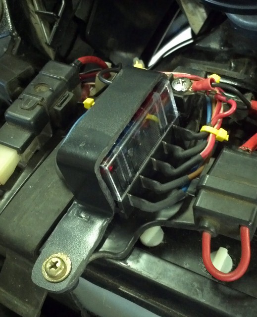
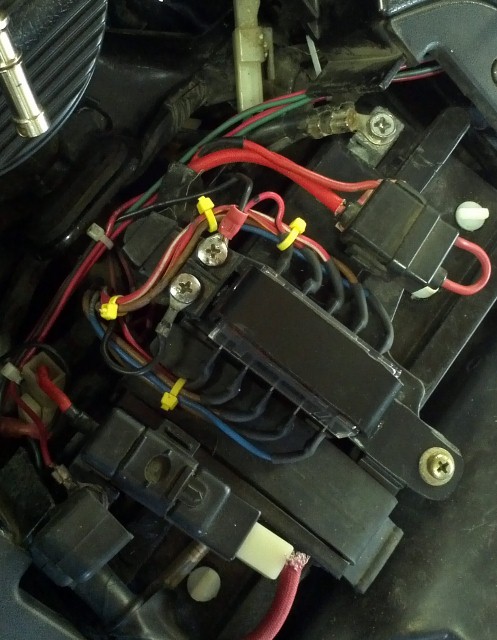
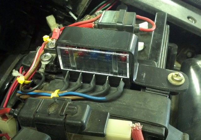
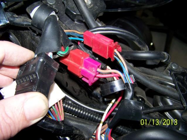
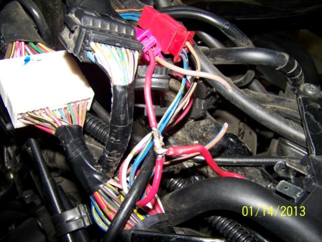
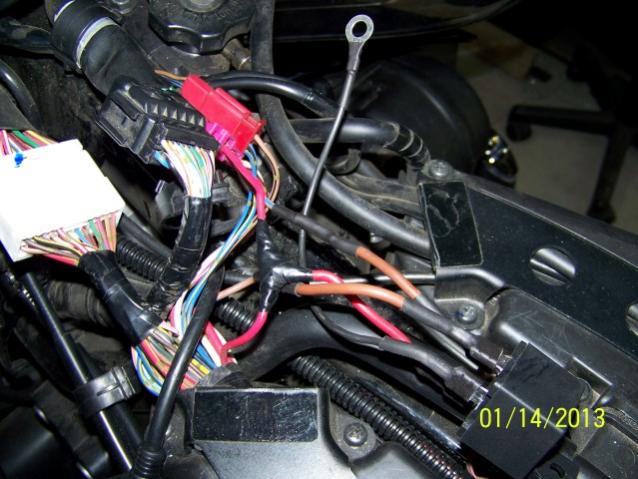
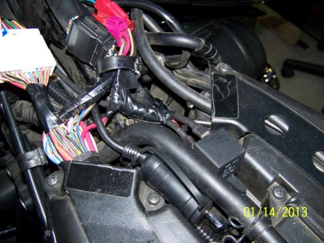
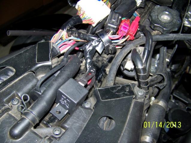
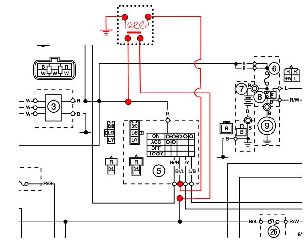
 There's been several times members here have by passed their ignition switch due to either switch failures or as a preventive to ward off failures. Today I decided to also do that to my bike and at the same time do a write up on it per a recent posting on this topic. For those who wonder why this is needed or desired the ignition switch has the majority of the power going thru one wire to feed lights and ignition requirements. Needless to say the switches contacts take a beating over time caused by overheating & normal wear & tear. The accessory part of the switch seems to never have this type of failure so this does lend credence to overloading on the one line being feed. By adding in a common 30 amp auto relay to that part of the circuit we can take the majority of the power off the switch before it gets there and route it directly to the line the switch powers, thus saving the switch. You'll need a couple of short 14 gauge wires, push on terminals, shrink wrap, and a 30 amp auto relay to do the job plus a soldering gun and wire stripper. To start you need to remove the drivers seat and gas tank. The gas tank is held on with a single bolt on the end by the seat plus two allen head bolts on the sides up front. Remove the cover by the ignition/gas cap. Disconnect the overflow vent hose and the fuel sender wires. The tank can be lifted off and set down out of the way now. Disconnect the (-) negative cable from the battery as you'll have one wire live otherwise. On top of the engine locate the wire harness coming from the ignition switch. There will be two red plug connectors going through a holder. Pull those out. The one you'll be working on will be the 2 wire one with a pink plug on one end disconnect that plug. Picture 1 shows it well. The next step is to splice a wire to the red wire with 14 gauge leaving it long enough to work with. Refer to picture 2 Cut the brown /blue wire leaving enough at the plug side to work with. Add a short length to both ends of the cut wire. Using a butt connector, soldered, and covered with shrink tubing will give a solid connection as well as protection . Add a female spade terminal to both of those ends. Do the same for the red wire spliced earlier too. Cover with shrink tubing after soldering them. Make a ground wire with a eyelet end on one end and a female terminal on the other. See picture 3. I used the closest bolt holding the radiator fill cap in place to ground the eyelet. The opposite end will attach to the relay. Connect the wires to the relay follows: spliced Red wire fastens to #30 terminal of the relay the brown /blue wire from the switch attaches to #86 terminal on the relay the brown /blue wire going to the harness connects to#87 terminal on the relay the gounding wire attaches to the #85 terminal on the relay. Wrap the wires up with tape and tuck them back into the harness holder. Pics 4 & 5 show the completed job with the relay as tucked in on top of the engine. Note: While this mod will prolong the life of the switch a long time there's always the posibilty that the switch can still fail through normal wear. If it does you can simply connect together the red wire and the brown/blue wire on the harness side to get you home. Some folks take this a step further and add a toggle switch between the two wires. I don't think it's neccassary on newer bikes but if you're experincing any ignition troubles now then I would certainly see the advatage of adding a toggle switch where you can get to it without having to remove the tank.
-
In a delima and was wondering if anyone has an answer to this for sure. If I go out state to look for work or just go there till my unemployment runs out can I still collect if I maintain a Michigan address. Now a days everything is done on line for UIA so it would make me believe this would be possible. If I needed to come back for work sign up and renew I could. My company has screwed me up so much I have been thinking hard about this. They are a little upset that I am drawing unemployment but they did not fight it. Weather or not they can down the road I don't know. It was kind of a communication gap between the U.S. terminal and the Canadian terminal that I had quit. to make a long storry short they didn't turn down my unemployment. Any comment's? Joe
-
I put the rear running lights on the + acc. terminal of my skydoc fuse upgrade. Then from the Acc. terminal to the switch, then to the rear lights. There is no relay in the circuit. It looks like the battery resistor mod is also on the same terminal. Question #1-Is it possible that when I turned on the lights that I could have blown the resisitor? It was fine during testing etc...but yesterday evening I decided to hit the switch to turn on the running lights and immediately my battery warning light started flashing and now it always on (with key on) Question #2 If I need to install a relay in the running light circuit, what do I ask for? Question #3 Does the battery resistor mod need it's own terminal?
-
As I get things together to do my fuse block install, various relay bypasses and, hopefully, repair of my ignition switch, I noticed something in a couple of other threads on the subject. When someone talked of installing a fuse block next to the battery so that accessories can be run off that rather than off the battery terminal, there were a couple of suggestions to put an in line fuse between the battery and new fuse block. Why? I mean, it is a fuse block - don't those fuses give you the protection you need? Why have a fuse between the battery and fuse block? There may be a good reason, but I just don't see it. Anyone? Andy
-
 I have a 08 RSV and getting ready to install a Biker's Choice tach. It says the green wire goes to the negative terminal on the coil. Is there a coil diagram available to show me where the negative terminal is? Thanks
 -
I installed an AGM battery and to turn off battery warning light I just sniped off the probe and connected the wire to a positive terminal of the fuse box and it seems to work fine. I just read the mod in the First Gen tech library and the post said to use a resister in the line before hooking the wire to a positive terminal. Is there some reason a resister should be used?
-
Now that I have been adding accesories to my 07 RSTD, the battery post are clogged with wires I attached. Is there a better way? Perhaps some kind of terminal block I could install. As always, you suggestions/recommendations would be greatly appreciated. Thanks Mark:bowdown:
-
Ok, my gauges (Equus) all work. Finished the install, changed the oil and cranked her up. Oil pressure came right up, water temp took a few and finally came up to about 180 degrees. Volts, no problem. The tach is not working. The light works but the needle does nothing. So here's the poop. I need some suggestions. The Tach is a Nitrous 2". I wired it as follows: White: Night lamp...tapped into the driving lights. Orange: Wired to the positive battery terminal. Black: Chassis ground. Green: To the negetavie lead on the coil. I am pretty sure it's the negative. According to the repair manual, it's the gray/orange (top terminal). My terminals are as follows. Red is the lower and white is the upper. So I connected it to the white terminal. Red: Is supposed to go to the ignition switch accessory position. I just tapped into the lights again since they come on when the key is turned to the accessory position. This may have been my down fall. I am not sure where to tap into the ignition at. I am not sure if it makes a differance or not. The tach does have a 4-6-8 cylinder switch. I tried all of these positions. Tech support was nooooooo help. Any ideas? I am bummed and pissed. I put alot of work into the tach housing. It really looks sweet, but it would look sweeter if the tach worked! Randy
-
It appears my solenoid maybe dead. I had a problem with the solenoid just clicking sometimes and sometimes the bike would not start at all sometimes I would press the start button several times and get nothing and sometimes I would get it to turn over. Now nothing no clicking no starting. Jumped the solenoid bike started right up. Disconected the Blue/white wire at the small terminal and put a test light and volmeter in between and connected to the positive terminal when I hit the start switch the test light lit up and when I used the voltmeter I got 12+ volts. So I'm guessing its dead a solenoid. I have searched the site for a small car/small engine replacement instead of the Yamaha one and havent been able to find a good suggestion of one to use anyone have one?
-
I need a few things for my new laptop running Vista home edition 32 bit. 1. A good USB serial cable adapter with drivers. 2. A terminal emulator program like hyper terminal or something else. 3. Will dos box run older programs? I'm trying to get the new laptop doing all I can. Tired of carrying two laptops just to maintain communications gear in the field. Now I got three computers on the truck.
-
My eyes are starting to get really tired from looking at almost 20 pages of posts about GPS hookups, 12 volt power outlets, hooking direct to battery, not doing that, fuse, no fuse, etc, etc. I have a 2005 RSTD. Here's my question: The aux DC terminal under the seat has a brown lead and a black lead, the 12 volt power outlet has a red wire and white wire. Does it matter which color is hooked to what? Also, is the aux DC terminal already fuse protected? Just want to make sure I do this right because I still have 47 payments left on the bike Seems like a simple question but I have been told that I often do the simple things with a deal of difficulty.
-
 So I (re)installed by stebel horn today with a relay relay post 85 to pink wire relay post 86 to brown wire relay post 30 to fuse block, which is connected to positive battery terminal relay post 87 to positive horn terminal negative horn terminal to negative battery terminal I also installed the Kury battery charge indicator. Pretty straight forward install. Use a pen light to locate switched on power wire. Light lights up when the key is turned to on position. Does not light up when key is turned to off position. The wire I used is green w/ a white stripe. It is part of a 3 wire block that is not used which is located on the clutch side of the bike. What I did was crimp a terminal (don't know the actual term) that can be used to push inside the wire block like how the stock blocks are used. Just looks like a thin flat piece of metal. Negative wire to ground. I had my battery tender hooked up and it is giving me a green light. Turned the bike on and the battery charge indicator is giving me 2 flashing red lights. I unhooked it and used my schumacher battery charger. It is also giving me a green light. Turned the bike on again and this time I get 2 red lights plus 1 yellow light which are flashing. So I am not sure why the battery indicator is telling me hardly any charge and the battery tender and charger are both telling me full charge. Any ideas why I am getting completely opposite results?
 -
In the owner's manual, it lists an Aux DC jack and Aux DC terminal. Is the jack the same on as that used for the audio headset? How do you use the Aux DC terminal? Could someone pls elaborate...thanks
-
Several folks asked me about the flag pole I had on the back of Blue Belle this weekend at Don's Maintenance Day. Here is the connection on e-bay for all that asked. I am not even going to try to remember who all asked me about it. http://cgi.ebay.com/ebaymotors/CHROMED-ALUMINUM-FLAG-holder-POLE-for-Motorcycles_W0QQitemZ300229722787QQihZ020QQcategoryZ84147QQrdZ1QQssPageNameZWD1VQQcmdZViewItemQQ_trksidZp1638Q2em118Q2el1247 I have the TERMINAL case of CRS (Can't Remember Squat). It is terminal, because the wife used to tell me she would kill me if I ever forgot her birthday or anniversary.
-
I have looked around and have not seen a specific write-up for the install of heated grips for the RSTD. So I thought that I would take a crack at writing something up based on my recent experience. The first thing that I did in preparation for this install was wire up a relay and terminal strip that I could use for power. I wanted power not just for this install but for future electrical accessories (lights, GPS, and communication system). I found great set of instructions for this at the Canyon Chasers site. Attached is a picture of how I installed mine under the seat (Relay.pdf). I tapped into an unused accessory plug that I assume is a leftover from the Venture wire harness. I tried to find something smaller than the terminal strip I used for distribution but it was inexpensive and it works. I have been unable to find the jumpers to energize the next terminal so I just made my own. I decided to retain the stock grips and install heaters from Dualstar. The price was a bargain (29.95 plus shipping) when comparing different heated grip systems. I struggled for a long time with where to install a switch. I didn’t want to spend much money on anything fancy, I didn’t want any bulky box or pod for switches and the RSTD doesn’t provide too many spaces to stick anything. I wanted something that was inconspicuous and settled on placing it in the plastic cover that conceals the frame and wiring that runs to the forks (Switch.pdf). I may regret this location because it isn’t easy to reach but I think the grips will be something I will not need to be flipping on and off frequently. If I am wrong with this location it will be easy enough to conceal and move on to something better when it comes to mind. The next challenge was getting the grips off. I took the counter weights off without a problem and used a small screwdriver and popsicle stick to pry loose the glue from the grips and worked them off. The next big surprise was the ridges on the throttle tube. I wasn’t expecting this and you must apply the heater to a smooth surface. With a lot of patience, a utility knife and a dremel I removed them and installed the heater element. The clutch side heater is about as simple as putting on a piece of tape and routing the wire down the bars. I did use the dremel to rework the chrome colar that goes with the grip to get a snug fit around the wires. I tested everything at this point and it was then that I ran into a snag. I had a short in the system. I called Dualstar. They helped me diagnose that the problem was on the clutch side and they sent a new one right away. They said they test every unit before it ships but I couldn’t see where I could have crimped or nicked anything thing to caused the problem. Regardless they took care of me. Moving on to terminating the wiring and powering things up… I had ran my power and ground from my terminal strip up under the tank to the switch and into the area under the chrome cowling that covers the speedometer display unit. Special Note: Removing that chrome cowling was a royal pain. It was held in place by three Philips screws that were installed with loctite and one head completely stripped out. Thanks heaven it was one on the out side, they are almost accessible. Had the center screw striped out I would still be standing in the garage swearing to myself wondering how to get it out. Needless to say I replaced the screws with Allen head bolts(Cowling.pdf). I soldered all my connections and put them in shrink-wrap tubing to keep things protected from vibration and the elements. The bundle of wires tucked up under the cowling neatly. I put things back they way they were and now I am waiting for the snow to melt and I can actually go for a ride. The heaters work great in the garage but I guess the big test will be in a few weeks when I can get out and go for a ride and see if they overcome the wind chill that my hands feel sticking outside the protection offered by the windscreen. Hope this helps any of you considering the install.
-
I ordered the CyclePump that is supposed to be the best air pump on the market. It cost me $100.00 plus the shipping. Saturday morning I checked my tires before a trip and I had 35 lbs in the front tire. I got out my cycle pump and was going to increase it to 40 lbs. When I turned on the pump the pressure went from 35 lbs down to 30 lbs. I was checking to make sure all the connections were good when the pump quit working. I plugged it into my car cigarette lighter and it worked fine, so I knew I had blown the auxiliary dc terminal fuse. The fuse for that terminal is a 5A. I replaced it with another 5A and when I turned on the pump it immediately blew that fuse. I got the instructions and read them and it says the cyclepump requires a 10-15A outlet. Would it hurt anythig if I changed the 5A fuse to a 10A? Thanks for your help.