


dingy
-
Posts
5,403 -
Joined
-
Last visited
Content Type
Profiles
Forums
Gallery
Events
Store
Everything posted by dingy
-
From the album: Hybrid 1st Gen/RSV/VMax project
-
From the album: Hybrid 1st Gen/RSV/VMax project
-

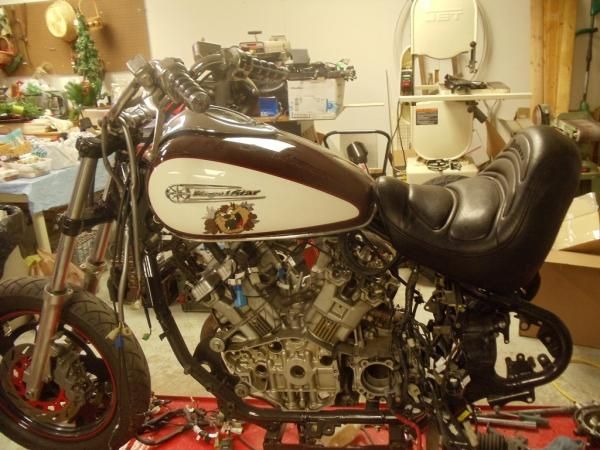
97 Royal Star tank setting on frame. Tank will be reworked by Ace High Leather.
dingy posted a gallery image in Member Albums
From the album: Hybrid 1st Gen/RSV/VMax project
-
You lived to tell about it, which is whats important !! Gary
-
One is Tweety, hybrid RSV may be christened Sylvester. Gary
-
1st gen front end is shown in pictures, but it is all or nothing as far as swapping out. Bearings & triple tree shaft are the same, but not much else. Diameter of fork tubes is larger on 2nd gen as well as centerline spacing of tubes. 2nd gen is about 2" wider than 1st gen. I removed the riser part from the upper tree on a 1st gen. Had to enlarge hole diameter to get 2nd gen risers to fit in upper tree. Did this because I want a smaller, more agile front end on bike. The RSV front is probably 25 lbs heavier than 1st gen. Front tire is huge compared to a 1st gen. Works nicely on RSV, but I am after a more responsive lighter feel. Gary
-
Picture of the dents on tank attached. Gary
-
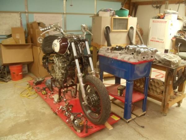
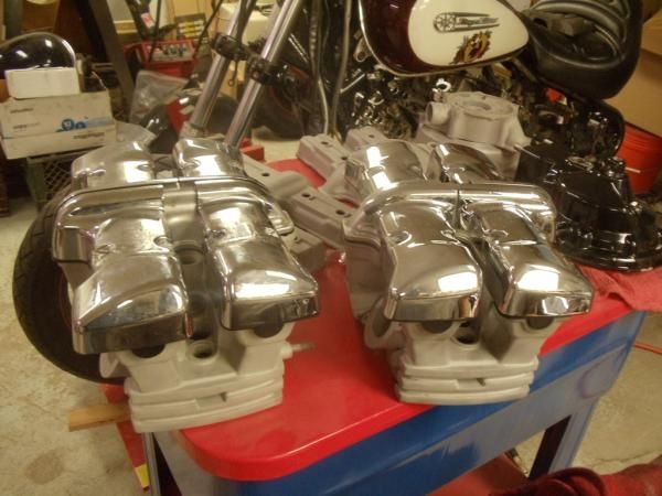
Some progress since last post and a couple of 'refinements'. Biggest noticeable change is the use of a 97 Royal Star fuel tank & instrument cluster. Tank has a couple of moderate dents on right side, so I got it at a very reasonable price, also have an instrument cluster & bezel for it. Tank will be stripped and painted. Cap & petcock fit from RSV tank and I got a fuel level sender from pinwall. Mounting is similar to RSV, but will need some tweaking on front two mounts and a revised rear mount. Went this route due to my VMax instrument cluster idea was going to be fugly. I will need to relocate ignition switch due to tank change also. I have a Royal Star final drive case, with needed sensor opening for the Royal Star instruments that I was going to put a VMax set of gears into that I have had for a while as a spare for Tweety. Turned out VMax gears had been swapped with Venture gears prior to my getting final drive. I have arranged a swap with a VMax re-builder for the needed gears. Going to use a set of RSV valve covers instead of the VMax covers. The motor is going to be completely powder coated gloss black. With the RSV covers I can put on a set of chrome caps that will be a nice offset to the black. Pictures of covers show them with tape residue that where on them from shipping, haven't cleaned them up yet. Swing arm has been blasted and painted with gloss epoxy spray paint. I was surprised that the swing arm would not fit in my powder coat oven due to 23" length, but the block halves will. Upper block is at machine shop getting the head decks milled .040" to raise compression. I have a single pick up coil & rotor that I am going to use in motor, instead of 4 pickup coil system that was in the 83-89 Ventures. Planning on getting another Marks collector for this one, then having a short set of 2" dia. mufflers made for it with insert baffles to tone it down a little. Stock style mufflers are not going to look good on this bike due to length. Gary
-
Don't get hung up on just the 2007 owners. The bike has changed VERY little since 1999. Gary
-
That now makes sense !! Thanks Jeff. Gary
-
side stand (kick stand)
dingy replied to WESTDYKE's topic in Royal Star Venture Tech Talk ('99 - '13)
What is area of concern about side stand? Portion of its function is in electrical section with starting circuits. Owners manual mentions it briefly in section 3. Other than that a search for "stand" didn't find anything else in service or owners manual. Gary -
Looking at pictures below, it can be seen that the sensor reads the revolutions of the pinion gear. The VMax/FJR gearing swap puts a 9 tooth pinion gear in the final drive in place of the stock 10 tooth pinion. Both gear sets have the same ring gear tooth count (33). Both gears should be changed though due to wear patterns on matching gears. When a VMax/FJR gear set is put in a stock Venture, the result is the RPM's increase when the bike is traveling at the same speed as prior to swap. This is about a 9% increase in motor RPM's at same ground speed. The result of this increase in RPM's is that the teeth on the pinion gear now pass the sensor 9% faster, given the same ground speed. What I don't understand is how this can not change the speedometer reading. If the input to the speedometer is 9% faster given the same ground speed, there has to be something I am missing. It's been a long week with doctors & hospital, so what is it?? Attached are some pictures of a couple of components of a Royal Star final drive case and a pinion gear. Ring gear is not shown in any pictures, but its teeth are on opposite side of the sensor/pinion interface point. 1st picture shows pinion gear laying beside case. [ATTACH]73680[/ATTACH] 2nd picture is case almost fully disassembled looking from what would be the inner (wheel side towards the pinion pocket (front of housing) [ATTACH]73675[/ATTACH] 3rd picture is same side of housing, but viewed down, now seeing the sensor pocket. [ATTACH]73676[/ATTACH] 4th picture isl looking from outside of housing with front on left. I have a yellow marker in through hole that pinion gear is in. [ATTACH]73677[/ATTACH] 5th picture shows pinion gear in housing, but not fully seated ( I don't want seat it at this time). [ATTACH]73678[/ATTACH] Last picture shows opposite side of housing with pinion in its pocket. [ATTACH]73679[/ATTACH] Gary
-
Sensor absolutely picks up on pinion gear teeth. Pinion is what changes in VMax gearing. It goes from a 10 tooth (Venture) to a 9 tooth (VMax). I have One of these apart right now in garage. I am putting gears from a VMax into a Royal Star drive. I needed the hall effect sensor to run the didital dash I am using on Hybrid RSV that came off a 97 Royal Star. Gary
-
Missing oil filter
dingy replied to donaldderby's topic in Venture and Venture Royale Tech Talk ('83 - '93)
Attached is a picture of what a bare oil filter mount looks like. Hole at 2:00 has to be plugged as well if oil is not leaking. Also attached is one style of a spin on oil filter adapter. Gary -
It won't be vacuum if the level increases during accel. and then stays the same. Vacuum would change depending on throttle position/motor loading. Gary
-
Service manual details it if you are refering to setting backlash between ring gear and pinion gear. Gary
-
Plates Earl produces are not cross connected, I have a set. It would be a much more labor intensive part if the pass through port where integrated into the design. If they were simply milled across on face of plate, o-ring would not work. Or a custom o-ring would be made, very costly for low quantities. Plate would have to be much thicker, the O-ring recess then made as a counterbore. Then cross dilled to connect the two counterbores, then cross drilling tapped & plugged on entrance side. Gary
-
They will be a metric size. If thickness of O-Ring is undersized it will not seal. Typically, 25% thicker o-ring than groove depth for anti dive type application. Gary
-
Made a sale of the steering head wrench to a buyer in Moscow, Russia today through Ebay. One of the farther out sales. Others have been, Canada, Australia, Czech Republic, Findland, France, Germany, Iceland, Ireland, Italy, Mauritus, Netherlands, New Zealand, Norway, Portugal, Slovakia, Spain, Sweden, Switzerland, United Kingdom and USA. But by far and away, Texas has gotten the lions share of the wrenches I have sold, almost 10% have went there. There are a bunch of Yamaha lovers out there. Gary
-
Those are Venture heads on motor and I don't think the carb rack has a v-boost on it. VMax heads have a different 'freeze' plug cover than the Venture's, fairly easy to spot. Nice sidecar though. Gary
-
Cause of the fuel pump failures
dingy replied to orlean1's topic in Royal Star Venture Tech Talk ('99 - '13)
I dissected the non working fuel pump that I got with my Hybrid/ RSV project bike and took some pictures that are attached. This pump was exhibiting very high current draw, basically a short circuit. Current draw did not reduce when points where opened. I got coil out of case and found that there is a diode across the incoming wires at the coil lead in wires. This diode had failed in a shorted condition which was causing the high current flow. Last picture shows aftermath of diode when I reversed polarity on it and it popped. Once diode was out of circuit, current draw on coil was in expected range. Below is a write up I did on a 1st gen pump, the RSV is very similar in functioning to what is in this thread. http://www.venturerider.org/forum/showthread.php?t=63062 Gary -
hazard lights only one side working
dingy replied to Seaking's topic in Royal Star Venture Tech Talk ('99 - '13)
Does right dash light flash when hazards are on? Looking at the wiring diagram, the hazard relay has a dark green wire that goes a junction point with the dark green wire (Dg on schematics) from the turn signal switch, then a dark green wire runs to the right front, right rear & dash bulbs. It is my profound opinion, that there is a break or loose wire between the hazard relay connector and the turn signal tie point. Below is a link to the redrawn schematics group listing I did a couple of years ago. http://www.venturerider.org/forum/showthread.php?t=42357 The specific sheet that will show what I am looking at is below. Look at lower left corner of sheet for flasher/hazard circuits. This page is shown without all the connector depicted. For complete circuits look at first page in thread above. http://www.venturerider.org/wiring/99-09%20Yamaha%20Royal%20Star%20Venture%20Simplified%20Circuit%20Diagram%20Rev%20B.pdf My usual disclaimer is that I have never worked on an RSV, now modified to not having worked on a complete RSV. Gary -
Wet problem
dingy replied to Venturous Randy's topic in Venture and Venture Royale Tech Talk ('83 - '93)
Take a look at the plug that connects the pickup coils to the main harness. 6 pin plug, 2x3 layout. 5 wires in plug, one empty slot. I have found this plug can be cause of bike not starting & or poor running. It is on left side near shock damper. I have a new spare connector set for this one & terminals if you need one. I sent this connector out with the last round of TCI's I sold, since I thought it was a problem area. Also still have new TCI's left if you want one. Gary -
The fixed fairing is what convinced me to get my original 1984 1st gen about 15 years ago. And not having that fixed fairing is a concern on the RSV/Hybrid project I am doing. I may end up putting a smaller 'Batwing' fairing on it to provide a termination point for wiring, headlight cover and some wind break. Gary
-
And Yamaha didn't kill a rather successful, albeit poorly marketed Venture only to resurrect it a few years later. 1st as a Royal Star, then the 2nd Gen Venture. Lets not forget the extremely popular VMax that was stopped in 2007 and then brought back a couple of years later. And how about Yamaha's narrow approach at naming their products. That annoying VMax snowmobile that is always coming up on Ebay searches comes to mind. Gary