.jpg.74ad527ee3b944bb2fbbda340f151e7c.jpg)
yamagrl
-
Posts
977 -
Joined
-
Last visited
Content Type
Profiles
Forums
Gallery
Events
Store
Everything posted by yamagrl
-
Another thought about putting it back on... How about that big nut? It might just force it on...
-
Flyinfool, I think you nailed it concerning the cage, balls and outer race. I think I would cut the inner race on two sides with a Dremel, being careful to not go all of the way through and damaging the shaft. That's going to be the easy part. I saw something similar on YouTube about changing head bearings. Once it's cut almost through on both sides snap/pry it apart. The hard part is going to be getting the new one on. I'm not sure it can be done so easily. Remember the spring? Which is more forceful; the spring or the force required to press the bearing back on? I don't know. It might just pogo you around. Maybe the shaft can be frozen with liquid something. Maybe the inner race on the new bearing could be heated. Perhaps a drilled and tapped hole into the end of the shaft and some kind of bearing pusher be invented to draw the bearing on, such as a reverse flywheel puller. I know it sounds like reaching for stars but then again ...who'd a thunk it anyway? Let's just get the old one off first. ChurchBuilder, What do you think? Heather
-
.thumb.jpg.c4a003e98a39017035bc287be592ba02.jpg)
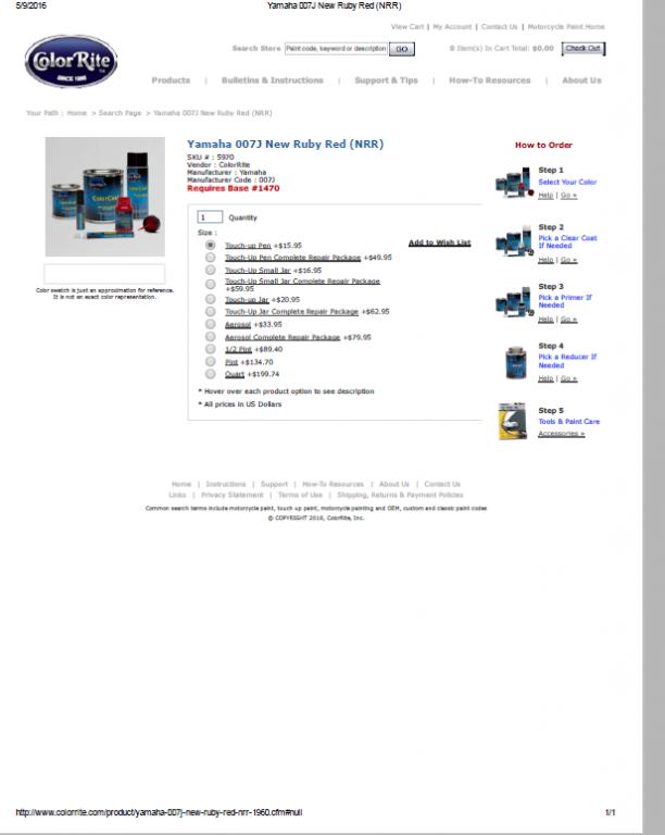
1989 VR Color Paint
yamagrl replied to videoarizona's topic in Venture and Venture Royale Tech Talk ('83 - '93)
Here is an example... ColorriteYamaha 007J New Ruby Red (NRR).pdf
-
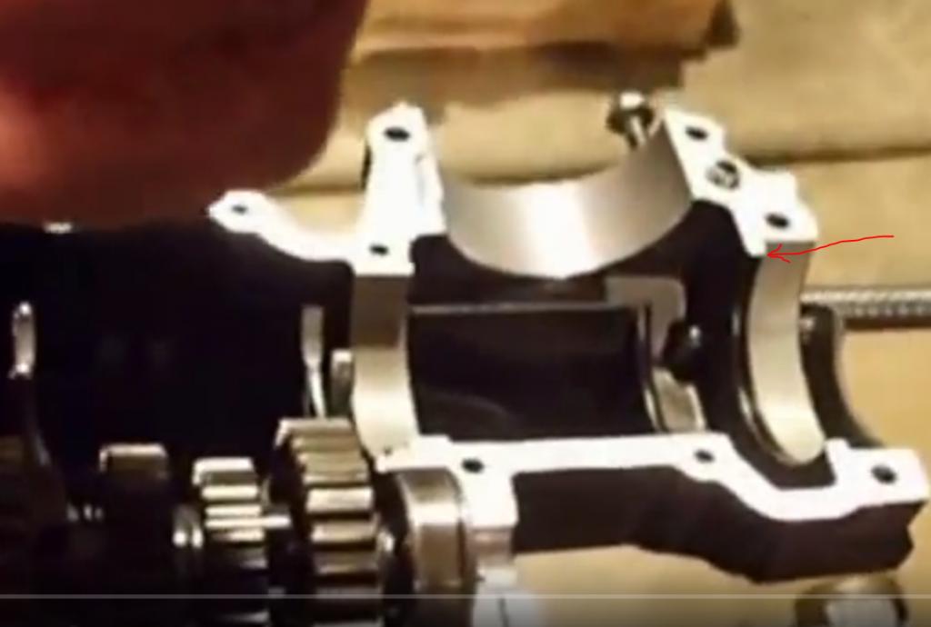
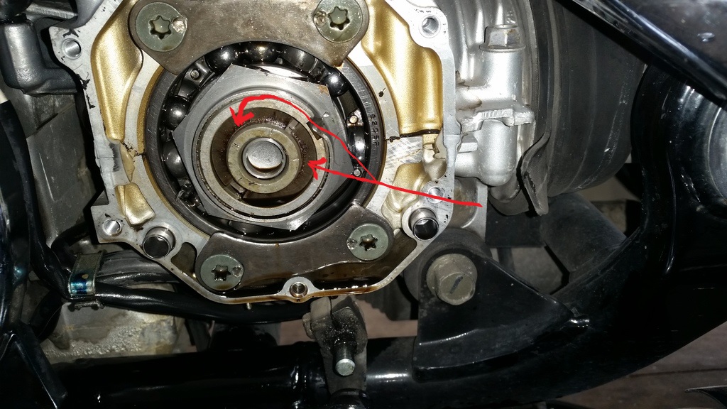
If it's possible to get the bearing out from the outside you will have to remove the nut. There is separator between the bearing and the gear. Compare the two photos below. The red arrow points to it.
-
The spring does not need to be compressed for the procedure that he is hoping to be able to perform without spitting the case. The middle gear in the above picture is only separated so that we could determine if that big nut could be loosened without the spring pushing everything apart.
-
Changing Steering Head Bearings
yamagrl replied to Flyinfool's topic in Venture and Venture Royale Tech Talk ('83 - '93)
We took it apart in pieces. Whether or not it's practical to do at Don's MD, I'm certain that he would know. -
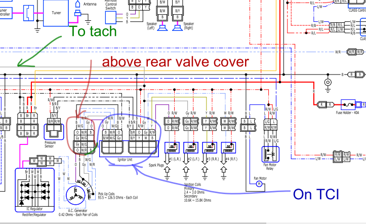
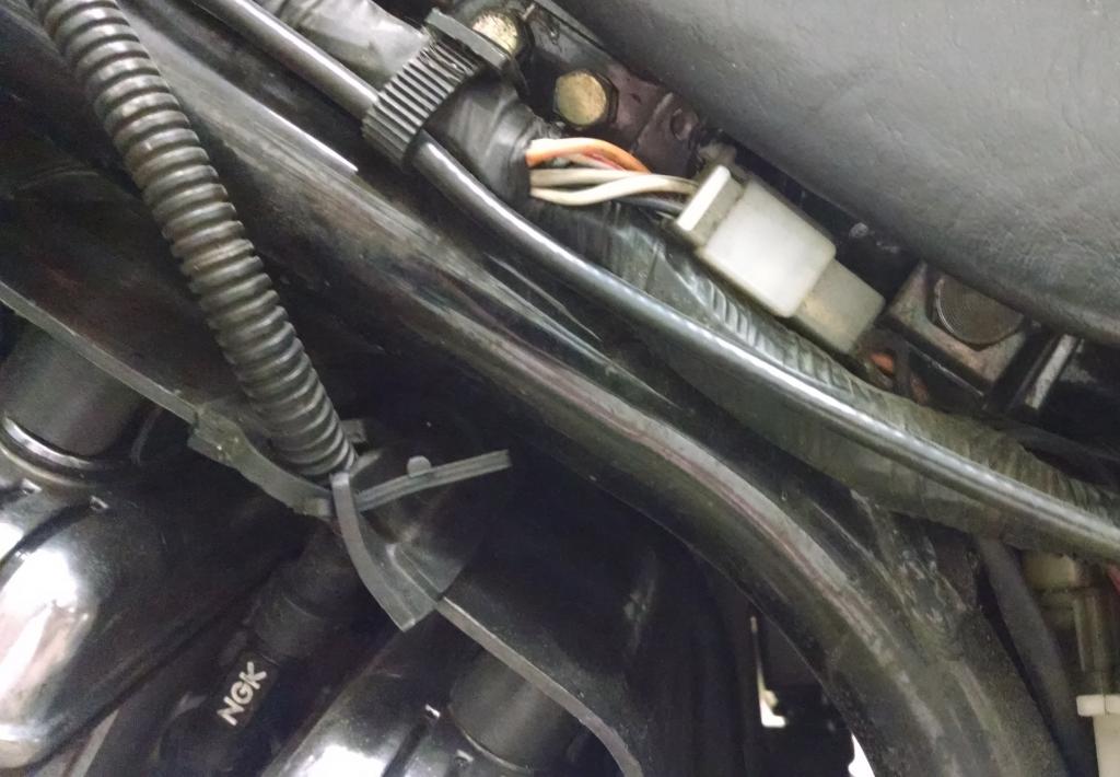
I told you wrong. The connector with the five wires that I was referring to is actually on the left side attached to frame, below the seat. It is not tucked in by the fuel pump. Sorry...My bad. In the pic #1 the green arrow points to the Grey wire going to the tack. The red circle is the connector that I have been talking about. This is where I would start. Dingy says that they are notorious for problems and in fact he includes a new replacement setup for this connector with his Ignitech TCI upgrade, (which would be an option if the TCI proves to be the culprit). This is what I'm betting on. The blue circle is the two connectors attached to the TCI In pic #2 is the connector I have been referring to. Tinker with it, clean it up, make sure it makes good connections. Then try to start it up before you go any further. Only the left side cover needs to be removed in order to gain access. If it still doesn't run after you have made certain that connector and the two on the TCI have good contact then your next thing to try is another TCI. Good luck. Heather
-
Changing Steering Head Bearings
yamagrl replied to Flyinfool's topic in Venture and Venture Royale Tech Talk ('83 - '93)
We did mine at Maint Day at Squidley's. And yes, your spanner is with the little bag of washers/spacers that I bought for the carb slide needles. H -
I concur. The tach is the dead give away. If I recall there is a quick disconnect tucked in around the area of the fuel pump that contains the five pickup coil wires that come out of the stator cover. These wires go into one side of the TCI. This is where the TCI gets its signal that it processes and sends to the coils. I would tinker with this one first since it's pretty easy to get to. TCI might be bad. I can take a picture of it on Big Red tomorrow. Heather P.S. Sometimes, I try to look at things as if there might be a reason... maybe there was a reason that you needed to be held up... you never know... just say "thanks" and accept it.
-
1989 VR Color Paint
yamagrl replied to videoarizona's topic in Venture and Venture Royale Tech Talk ('83 - '93)
I emailed Colorite a couple of years ago because mine wasn't listed. They promptly replied and said I could still get it. -
I just recently bought a set of blue dots on ebay. One thing I was paying attention to was the pads. I paid $60.00 for the pair I ordered which has about 75% of the pads left. Good pads are $35.00-ish x two. If you're doing all of this you might want to replace the fork seals while you have it apart. Technically, you only need the lower fork tubes. So if you replace the fork seals then you may use the best set of upper tubes. If you use the existing upper tubes then it can be done on the bike. There's a couple of articles in the Read Only Section and a couple of videos on Youtube. Here's one on how to do it on the bike. I installed Progressives last year. I used about 1 inch of preload spacer and it raised the font end up too much and the bike wandered a lot at slow speed like when traffic was creeping along. It was very difficult to control. So I took out the 1 inchers and put 1/2 inchers in. That took care or it. Many people state that these bikes are top heavy. That's simply not true, at least with the Mk1. If the front is aired too much then they become "front high" and that makes them wander and seem top heavy. The gas tank location lowers the center of gravity considerably. Heather
-
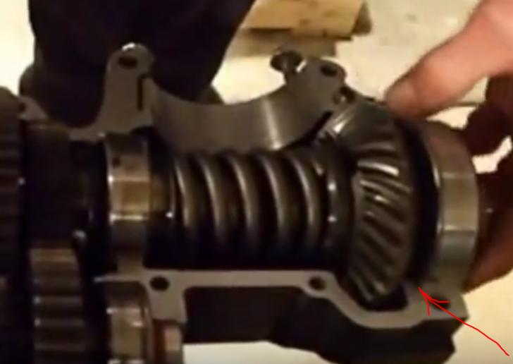
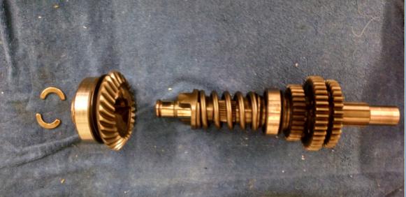
I separated the two main sections of the middle gear shaft. You will not have to worry about things popping apart. I de-staked and put the bearing section into the vise and attempted to unscrew that big nut and zero luck. I couldn't turn it. But then I didn't "go on a mission" to get it off. I simply determined that it's on pretty tight. Theoretically the bearing can be changed from the outside. But, I think you will be faced with two or three challenges: The outer portion of the bearing is going to be pretty tightly squeezed into the case. This may prove to not be very problematic. You might be able to lessen the squeeze by de-torquing the case bolts in the immediate vicinity, being mindful to not actually break the seal of the case halves. But even if you do, an oil leak may not even occur or be minimal. Cross your fingers. The nut may be very hard to turn and you may be exerting a pretty significant force on the gears in the transmission. The bearing may be pressed on. "Take a stab at it" Here is a pic of the separated middle gear.
-
Out of the abundance of the heart the mouth speaks.
-
Kind of a double whammie I guess! Oh well...
-
How are you supposed to make a clean getaway when your that lit up?
-
I've been researching this morning. I think the infamous thrust washer may very well prevent the spring from pushing everything out. But I won't know until I can take one apart in my shop. I also think it may be nearly impossible to remove the bearing since it is kind of held very snuggly between the upper and lower case halves. But on a positive note there is no "positioning pin" on this bearing like on the other two on the middle gear shaft.
-
making rear turn signals running lights?
yamagrl replied to DblTrbl's topic in Poor Man Tips and Fixes
Our Roadstar 1600 has the rear signals converted to run/brake/turn. It also has a short led strip addon attached to the license tag that is run/brake. The led strop really lights up in both run and brake, but the converted signals not nearly as bright and in some light such as the sun behind you the turn signal flash is not very noticeable. In fact when I'm riding behind Rachel on the Roadie sometimes I can barely see the flashing turn signal. Our Vstar 1100 has the original setup and the amber signals are exceptionally noticeable in all lighting conditions. We have decided to return the 1600 back to the original state or at least remove the run circuit from them and go back to Amber bulbs. That would give additional brake lights but not violate the "only constant red lights on the rear laws" -
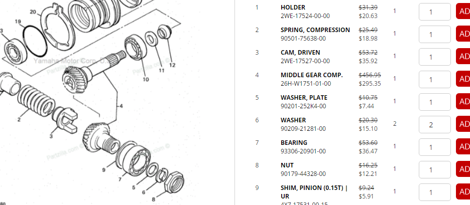
I'm not too sure about that. The red arrows in the photo (item 6 in the breakdown) are pointing to the exact thrust washers that are the cause of the infamous second gear issue with the early 1st Gens. The middle gear has be placed in a hydraulic press in order to compress the huge spring on the middle gear so as to remove and replace those half moon thrust washers. I think you might have to remove those trust washers too, but I'm not 100% certain. I'm afraid that if you remove the middle gear retainers and remove that big nut that you might not like what happens next. So just let me check for you. I have an old middle gear out in my M/C shop/garage. Tomorrow or Saturday I will see exactly how it comes apart. I'll take a pic or two for you. I'll be able to determine if it can be done in place or not. Certainly, if it can be done in place that's what you would want to do. Flyinfool what do you think?? Heather
-
Normal?
-
Starter just quit
yamagrl replied to Dragonslayer's topic in Royal Star Venture Tech Talk ('99 - '13)
I'm now officially a "Junior Dragonslayer"! -
Starter just quit
yamagrl replied to Dragonslayer's topic in Royal Star Venture Tech Talk ('99 - '13)
Bob, It was my pleasure to help, because... I get off on '57 Chevys; I get off on screaming guitar. Like the way it hits me every time it hits me. I've got a rock and roll, I've got a rock and roll heart. -
Starter just quit
yamagrl replied to Dragonslayer's topic in Royal Star Venture Tech Talk ('99 - '13)
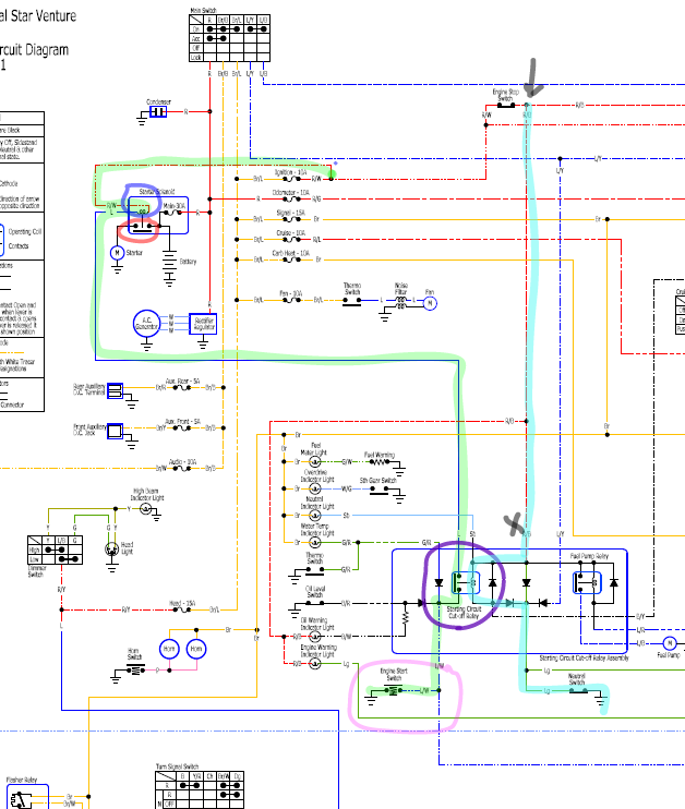
Sometimes it just takes another set of eyes. For those of you who might be wondering how it all worked out. See photo below. (for the following procedures we are ignoring the existence the diodes and the Fuel Pump Relay within the SCCR because they are not presenting any apparent problem at this point) On the lime green highligted circuit, Bob and I verified current on 12V on R/W at the solenoid 12V on L at the solenoid 12V on L at SCCR (Starting Circuit Cutoff Relay) ...but no current at the L/W on SCCR We verified continuity through the Engine Start Switch to ground That meant that the SCCR internal contacts were not closed/activated. In neutral with ignition on and Engine Cutoff Switch in run position The SCCR internal contacts should always be closed, thus allowing current to make it's way through the lime green highlighted circuit from the ignition fuse all the way to ground at the Engine Start Switch causing the Starter Solenoid to engage the starter motor. So now we had established that the problem was in the coil side of the SCCR circuit (light blue highlighted circuit) We then began our trace at the (X) on SCCR to determine whether the problem was north or south of the SCCR. No current at R/B at SCCR (X) Went north to the connector for the Engine Stop Switch (arrow) Engine Stop Switch in Run 12V on R/W at the connector but... No current on the R/B at the connector. So we fooled around with it a bit, got 12V , hit the start button and... VAROOM! Another dragon slain!
-
before you dis-own or hate me...
yamagrl replied to Great adVENTURE's topic in Royal Star Venture Tech Talk ('99 - '13)
Add the amount of the additional height to the length of the existing cables. -
3-5 gear problems
yamagrl replied to Jpischke's topic in Venture and Venture Royale Tech Talk ('83 - '93)
I'm assuming (you know that that means...) that it's a 1st Gen. What year? When you say "it won't budge past 2nd" do you mean the shift lever: 1. That it can be raised basically the normal travel but really does nothing... just moves up and down? If this is the issue it sounds like one of the shift segment pins is at fault. (That's what Puc is talking about) OR 2. That the shift lever really can't be moved up at all... it just will no longer budge? If this is the case it sounds more like one of the shift forks or the shift drum. With the clutch lever out, can you rock the bike back and forth and make it shift up through 3rd, etc.? I'm traveling this weekend, but will try to keep up with your thread. Heather -
French Connection