.jpg.74ad527ee3b944bb2fbbda340f151e7c.jpg)
yamagrl
-
Posts
977 -
Joined
-
Last visited
Content Type
Profiles
Forums
Gallery
Events
Store
Everything posted by yamagrl
-
Can't ya just put a 30 and a 25 in the blender and come up with something pretty close to a 55?
-
.thumb.jpg.c4a003e98a39017035bc287be592ba02.jpg)
Brake line lengths
yamagrl replied to yamagrl's topic in Venture and Venture Royale Tech Talk ('83 - '93)
I found it. http://www.venturerider.org/forum/showthread.php?48559-Brake-hose-description-list&p=472651#post472651 dingy 7 Attachment(s) Brake line measurments Here is a list of lines I have from my 1st gen 83. I would treat these numbers as reference only. I tried to get accurate measurements though. Rear Master to rear caliper. 18 3/8" from C/L to C/L of banjo fittings. One banjo fitting @ 15 deg. Both banjo fittings rotated @ 90 deg. to each other Attachment 45183 Rear Master to front steel line at rear master. 4 3/4" from face of 10mm fitting to C/L of banjo fitting. Banjo fitting @ 15 deg. Attachment 45160 Front metering valve to front caliper. (This line is from a 1988 bike with the upper bleeder port). 8 5/16" from face of 10mm fitting at top bleeder to C/L of double banjo fitting. This segment would be eliminated for 83-85 models without upper bleeder port if desired. 33 3/4" from C/L of double banjo fitting to C/L of banjo fitting at brake caliper. Banjo fitting at brake caliper @ 15 deg. Bottom banjo fitting is rotated @ 90 deg to double banjo fitting. Attachment 45157 Front master to brake caliper. 44 1/4" C/L to C/L of banjo fittings. Top banjo fitting @ 15 deg. Bottom banjo fitting @ 15 deg. Two banjo fittings are in line with a combined angle of 30 deg. Attachment 45155 Anti dive valve. (MKI only) 11 1/2" C/L to C/L of banjo fittings. Attachment 45159 Top clutch line 22 1/2" C/L of banjo fitting to face of 10 mm fitting. Banjo fitting @ 15 deg. Attachment 45161 Lower Clutch line 8 1/2" C/L of banjo fitting to face of 10 mm fitting. Attachment 45158 -
What are the clutch line length and the front and rear brake lines lengths? I recently saw a post that said how long the brake lines are, but for the life of me I just cannot find that post again. Heather
-
Anyone interested in a M & E rally near Atlanta this summer?
yamagrl replied to Dragonslayer's topic in Watering Hole
Most likely. -
83 venture royal bobber wiring help
yamagrl replied to Ajslay's topic in Venture and Venture Royale Tech Talk ('83 - '93)
These wiring diagrams are amazingly easy to read and understand. On this forum there are Simplified diagrams and then there are Wiring diagrams. The Simplified diagram provides a wonderful conceptual view of the electrical system. Use the Simplified to figure out what you want to achieve. Theory Once you figure out how the specific components work then refer to the Wiring diagram. It is very concise and even shows the wires in their respective position within the connectors. http://www.venturerider.org/wiring/83%20Yamaha%20Venture%20TK%20Simplified%20Circuit%20Diagram%20Rev%20C.pdf http://www.venturerider.org/wiring/83%20Yamaha%20Venture%20TK%20Wiring%20Diagram%20Rev%20C.pdf Heather -
Looks like fun to me...
-
lost 4th and 5th gear
yamagrl replied to mike042's topic in Venture and Venture Royale Tech Talk ('83 - '93)
Here it is http://www.venturerider.org/forum/showthread.php?40713-Clunky-Shifting -
Any updates?
-
lost 4th and 5th gear
yamagrl replied to mike042's topic in Venture and Venture Royale Tech Talk ('83 - '93)
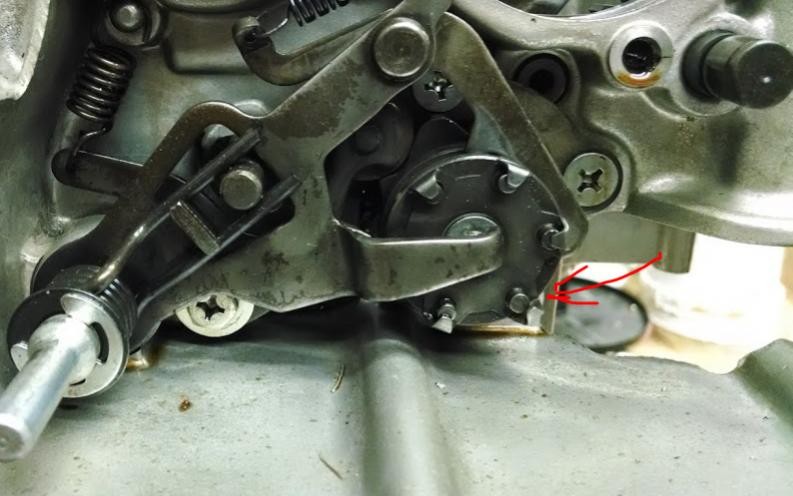
I suspect that the shift segment pin for fourth gear has fallen out. In the pic below you can see that some of the keepers over the pins has become distorted. Once they get bent enough the pin just falls out. These are part of what rotates when you move the the shift lever. I suspect that the one for fourth has come out. It has to go into fourth before it can go into fifth. The part is here. Item 7 is what I suspect has fallen out. Item 8 is what I suspect is why. http://www.partzilla.com/parts/search/Yamaha/Motorcycle/1983/XVZ12TDK/SHIFT+CAM+-+FORM/parts.html The shift segment in the 2nd gens were a better design and it is common to upgrade to these in the 1st gens. Here it is in the 2nd gen. But I would recommend to just fix the existing, install a new pin. The old pin may still be in that area around the clutch but maybe not. Mine found its way into the oil pan. Items 4,5,6,7&13 http://www.partzilla.com/parts/search/Yamaha/Motorcycle/2000/VENTURE+MM+LIMITED+EDITION+-+XVZ1300TFSM/SHIFT+CAM+FORK/parts.html
-
I can attest to that!
-
Changing Steering Head Bearings
yamagrl replied to Flyinfool's topic in Venture and Venture Royale Tech Talk ('83 - '93)
...tell me about it... -
I got his email off of his thread that I linked on that post. I have not tried it but likely will be in the near future.
-
...house Rock
-
Huh?
-
Leaving...
-
Flowers
-
Here is Dano's profile. Looks current to me http://www.venturerider.org/forum/member.php?2796-Dano Here is the Starter clutch mod thread.http://www.venturerider.org/forum/showthread.php?44547-Starter-Clutch-Mod Dano's email danob11@comcast.net
-
Dues
-
Did I broke it?
yamagrl replied to Fl Hermit's topic in Venture and Venture Royale Tech Talk ('83 - '93)
I wouldn't think the pickup coils themselves would be the problem either, but perhaps the wire connections or quite likely the tci -
Did I broke it?
yamagrl replied to Fl Hermit's topic in Venture and Venture Royale Tech Talk ('83 - '93)
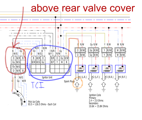
Most people here would agree that the ignition system is pretty simple to troubleshoot. There is only about 4 basic steps and I'll outline them for you below. I have also highlighted the #1 cylinder ignition circuit in orange. You can see from the diagram that it is actually quite simple. Since you are getting spark on #1 that means we know that you are getting current to the ignition system. 1. Check all obvious things such as both ends of coil wires, new or known good spark plugs, broken wires, etc. Check the air in the tires (joke) Tune the radio to Classic Rock (This one is Very Important) 2. Check the connector with 5 wires that is attached to the frame on the left side, below the seat (see pic below. It is also circled in red in the diagram below). Make sure that it is clean and has continuity (a good connection through both sides of each wire). You can do this with a multimeter. Side note: At the south end of those wires is the Pickup coils that are located in the left side engine cover and the north ends go the TCI (Ignitor Unit on the diagram). 3. Ensure that the 2 connectors on the TCI are clean and firmly connected (circled in blue). The TCI is located below the battery and above and kind of forward of the engine 4. Make sure that the small 2 wire connector on each coil is securely plugged in. (4 in all) and that there is 12V on the Red/white tracer line on each one of these 4 connectors. You have now pretty much traced out the entire ignition system. If all of your connections are good then the next thing is to try another TCI that is known to be good.
-
Date
-
Forks bottoming out
yamagrl replied to kapebretoner's topic in Venture and Venture Royale Tech Talk ('83 - '93)
I bought a pair last year and that's about what I paid. -
Forks bottoming out
yamagrl replied to kapebretoner's topic in Venture and Venture Royale Tech Talk ('83 - '93)
$76.63 free shipping in US. Canada shipping and import adds about $25.00 http://www.ebay.com/itm/Progressive-Suspension-Fork-Springs-For-Honda-Kawasaki-and-Yamaha-11-1112-/361274075221?hash=item541d9ce855:g:PPwAAOSwqv9V51N7&vxp=mtr US dollars, Canadian Dollars... Just numbers that reflect the universal value. Change to yen, you get different numbers again. -
1st gen vs 2nd gen clutches
yamagrl replied to gaj1917's topic in Venture and Venture Royale Tech Talk ('83 - '93)
Yes. If you have the entire 87 clutch it will fit in an 84. If you do not have the complete 87 clutch then you would need to compare the parts breakdown in order to determine which parts of the 84 remained as part of the 87 clutch. I did a quick comparison on Partzilla http://www.partzilla.com/parts/search/Yamaha/Motorcycle/1987/XVZ13DT/CLUTCH/parts.html The items that I found different from the 84 (old)in the 87 (new) are 3,6,1213,14,15,17,20 (don't miss this one), 21,23 (Be sure to verify this for yourself) What I did was open the Partzilla 87 clutch breakdown. Individually click on each part. That part will pop up. Scoll down and it shows you the other M/Cs it was used on. Look for 84. Click the back arrow and go to the next. The other thing that is needed is clutch cover. It is slightly wider in order to accomodate the new style clutch. Cover, crankcase 3. Item 24 here http://www.partzilla.com/parts/search/Yamaha/Motorcycle/1987/XVZ13DT/CRANKCASE+COVER/parts.html -
Puc, I think you mean "between the battery and the CPU Monitor (not tci)
.jpg.a5ca966f824eefe9261eb88aa975f0fc.jpg)