dingy
-
Posts
5,403 -
Joined
-
Last visited
Content Type
Profiles
Forums
Gallery
Events
Store
Everything posted by dingy
-

crankshaft question
dingy replied to quant55's topic in Venture and Venture Royale Tech Talk ('83 - '93)
Attached a picture from another thread regarding this block, if it is the same one. There is some significant damage under the near main bearing in picture. That may be cause noise you are hearing., Maybe not, but a good starting point. Post #15: http://www.venturerider.org/forum/showthread.php?p=822076#post822076 Gary -
jet kit with out drilling
dingy replied to speakerfritz's topic in Royal Star Venture Tech Talk ('99 - '13)
Drilling plugs out is primarily to adjust idle mixture. This is one of the basic steps most often taken well in advance of re-jetting. Shimming of needles is a separate issue. What are your expect to gain from re-jetting. Any air box or exhaust changes? Have you gotten a base line A/F reading to see what needs to be changed? Gary -
Aftermarket TCI available!
dingy replied to tvking63's topic in Venture and Venture Royale Tech Talk ('83 - '93)
Sorry, I don't understand previous post ??? Gary -
Aftermarket TCI available!
dingy replied to tvking63's topic in Venture and Venture Royale Tech Talk ('83 - '93)
You have what Ignitech is supplying. Attached is a PDF file showing how I wire cables to use after market Sensor. I included some pictures of harness that has MAP wires added. I don't see a major difference between IAP & TPS settings other than the IAP settings are variable on left side of advance graph. The usage of either setting is dependent on an external sensor to vary a 0-5vdc signal in response to changing air pressure values. I have a TPS in place on Tweety, I just haven't hooked the Ignitech up to it. couple of pictures of what I did. 3D printed a modified spool in the throttle junction block to drive TPS. Gary -
Aftermarket TCI available!
dingy replied to tvking63's topic in Venture and Venture Royale Tech Talk ('83 - '93)
I tried the setup shown in attached pictures. I used a 5 port Vacu-tite fitting to tie the 4 sync ports together. The 5th port ran to a 1 1/2" PVC pipe with a cap on both ends. I tried several lengths of the chamber and the shortest possible worked to smooth out pulses while still not inducing to much lag. Not using it now, just running vacuum from #2 port. Gary -
New intake boots - torque?
dingy replied to Jinksy4's topic in Royal Star Venture Tech Talk ('99 - '13)
If it's looks like you could get a long drill down in there to put a helicoil in with. The tap drill to put a 6mm helicoil in is 1/4", closest American drill. This is an easy drill to find in an extended length. The helicoil uses 7mm tap to prepare for coil. As far as the tap drill for the existing holes being drilled through into oil pocket, this was knowledge of 1st gens, I don't know if the 2nd gens have same issue. Gary -
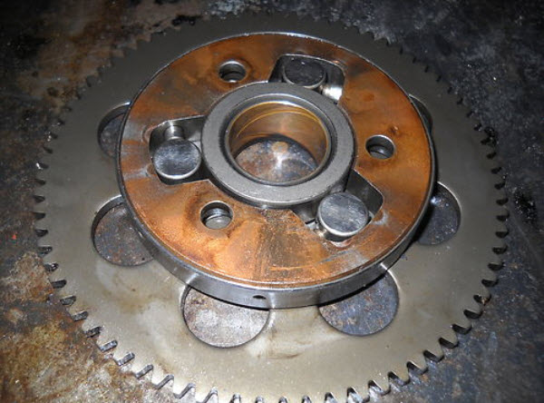
Time for second gear repair
dingy replied to yamagrl's topic in Venture and Venture Royale Tech Talk ('83 - '93)
I'm a happy camper with my Dano starter clutch. Tweety was starting to have issues. Higher compression in motor was accelerating failure. Picture of reworked rotor I got back from Dan attached. Also picture of stock starter clutch assy., removed from rotor. Rather puny in comparison. Gary
-
Vmax Cam install help... Please?
dingy replied to Reaney in NH's topic in Royal Star Venture Tech Talk ('99 - '13)
Pictures attached indicating timing holes in VMax camshafts. #1 is both cams side by side #2 is exhaust cam small hole #3 is exhaust cam large hole #4 is intake cam small hole #5 is intake cam large hole (180 deg from small hole+/-) Gary -
Wayne, There is "14" cast into master reservoir near banjo bolt port on the 9/16" units. 14mm roughly equals 9/16" (.5511") 1/2" masters had "1/2" cast on them. Don't know why fractions once & metric on later unit. Gary
-
Since you delinked the brakes, it would be helpful if you put a 9/16" master on at this time. That will give you more volume to drive the doubled caliper piston volume. MKII's had 9/16" brake master's. MKI's were 1/2". Gary
-
Check the connector from the pickup coils to the harness. This is near rear shock dampener, left side by passenger footrest. There are (2) six pin connectors in that area. Pickup coil is one with 5 wires in it. I have seen this connector cause intermittent operation before. Gary
-
Mystery part...What is this pin?
dingy replied to yamagrl's topic in Venture and Venture Royale Tech Talk ('83 - '93)
It is not a bearing retainer pin, they are far smaller than size of found pin. There are no needle bearings in block near this size. It is a shifter pin. Gary -
Yes. Gary
-
Time for second gear repair
dingy replied to yamagrl's topic in Venture and Venture Royale Tech Talk ('83 - '93)
Torch. Not red hot though. Google Red Loctite specifications Gary -
Time for second gear repair
dingy replied to yamagrl's topic in Venture and Venture Royale Tech Talk ('83 - '93)
Also #4 & #8, old screw is hard to remove cleanly. Use heat on it to break loctite. Gary -
Time for second gear repair
dingy replied to yamagrl's topic in Venture and Venture Royale Tech Talk ('83 - '93)
Picture of upgrade shift segment attached. You do not need the plate at top left, old one is fine. Picture of parts break down attached & link to page. http://www.partzilla.com/parts/search/Yamaha/Motorcycle/2003/ROYAL+STAR+MIDNIGHT+VENTURE+%28Onyx%29+-+XVZ1300TFSR/SHIFT+CAM+FORK/parts.html The shift segment pins will be hardened steel, not easy to cut at all. All needed pins are about $10. Shift segment is $33.32 Gary -
Some pictures of the Hybrid as it progresses. Heel toe shifter replaced with a 1st gen pedal. Head light is dual projector units with HID unit on high beam. 2nd gen master cylinders may not work on the 1st gen bars due to angle of reservoir body, 1st gens are angled so top is parallel to ground. 2nd gens are at a quite an angle. I can install 1st gen masters if 2nd gens don't work out. Front shock spring adjustable pre-load spacers installed. 1st gen rear rotor, 320mm floating, mated to 2nd gen caliper. Front end is entirely 1st gen, except calipers, these are from YZF750 Yamaha 1997. 6 piston units. Gary
-
Time for second gear repair
dingy replied to yamagrl's topic in Venture and Venture Royale Tech Talk ('83 - '93)
Shifter segment in attached picture. You have one on right side. Parts breakdown it is in Shift Cam section Gary -
Time for second gear repair
dingy replied to yamagrl's topic in Venture and Venture Royale Tech Talk ('83 - '93)
Fairly sure it is a gear shift segment pin. Clutch side, lower rear of case. Gary -
Vmax Cam install help... Please?
dingy replied to Reaney in NH's topic in Royal Star Venture Tech Talk ('99 - '13)
Attached is PDF section from VMax service manual on replacing cams. It may vary from RSTC. Gary VMX12- Service-Manual Cam install.pdf -
Aftermarket TCI available!
dingy replied to tvking63's topic in Venture and Venture Royale Tech Talk ('83 - '93)
You also have third option of Manual setting. In attached picture, I drew an arrow to the 3 settings that are added when Manual dwell is selected. I have not worked with this setting though. It would seem that shortening the dwell time would help. Gary -
Aftermarket TCI available!
dingy replied to tvking63's topic in Venture and Venture Royale Tech Talk ('83 - '93)
The Ignitech can use either the stock Venture sensor or an aftermarket sensor. A one bar sensor is best option. I include an aftermarket unit that is wired into adapter cable. There were a couple of issues that drove the new MAP sensor. 1st, the stock sensor is a 12v output. Ignitech said 12v would be OK with TCI, which is 5V based input/outputs. 2nd, by supplying a new MAP, there was a known good replacement for the stock sensor, which has been known to have failed. I have been using TPS setting on units I sell. MKI, MKII and VMax settings are similar for MAP settings, no substantial differences. Gary -
Peek inside my TCI if you will
dingy replied to Razorback's topic in Venture and Venture Royale Tech Talk ('83 - '93)
Pin outs shown in attached picture of where traces go to on board for connectors pins. You probably don't need this since you cut box open. Handy to have where pin ended up in case a trace was damaged when soldering pins. Picture of board shows replaced diodes. They don't have to be right against board. It is easier to leave them higher up, then a heat sink, like an alligator clip can be attached to longer leg. Gary -
Peek inside my TCI if you will
dingy replied to Razorback's topic in Venture and Venture Royale Tech Talk ('83 - '93)
Attached are some pictures of one I cut open. Very center of board, there is a component I cut with band saw. Also a picture of section I cut out. This is a very bad one inside. It wasn't working. Gary -
exhaust for a MKII
dingy replied to GAWildKat's topic in Venture and Venture Royale Tech Talk ('83 - '93)
Collector on Ebay that ends tonight. http://www.ebay.com/itm/1983-1993-Yamaha-XVZ1200-1300-Venture-Center-Chamber-Rear-Headers-NICE-4085-/310966180935?pt=Motorcycles_Parts_Accessories&hash=item4867075c47 Gary