syscrusher
-
Posts
848 -
Joined
-
Last visited
Content Type
Profiles
Forums
Gallery
Events
Store
Everything posted by syscrusher
-

super brace
syscrusher replied to adventurer 08's topic in Venture and Venture Royale Tech Talk ('83 - '93)
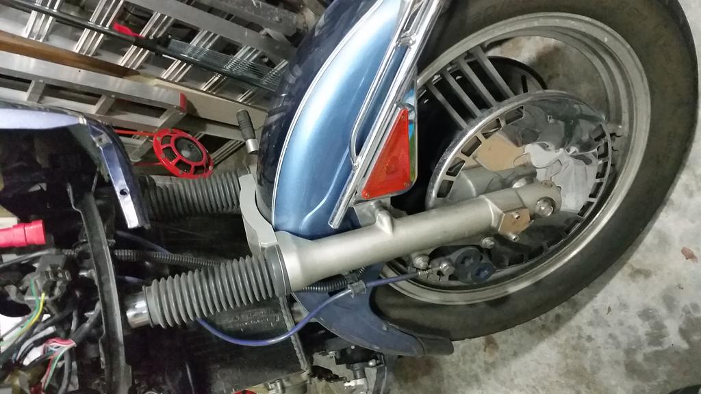
I looked it up, it looks like I bought it in October of 2014. You weren't selling yours at the time and someone posted this one. It looked good to me and so I jumped on it. I did notice that Ebay shows the listing as ended July 1st so the trail's not so cold: Ended: Jul 01, 2016, 7:37AM After my April accident in 2015 I replaced the front forks and installed this brace. I like it. Here's what it looks like on a Gen 1.2, what you see is safety wire wrapped around the bottom of my dust boots. I had to cut away the rubber on the insides of the boots, leaving only a small bead on the bottom. The fork brace was very slightly radiused on the bottom inside and the fork slider itself has a groove in that location all the way around. It was just enough room for me to mash my retention system in place as the brace was installed. It's a tighter fit than it ever could have been without the extra material. Shimmed to the max. Let us hope I don't need to replace fork seals or anything of that sort for many years to come. Chunky Brace
-
super brace
syscrusher replied to adventurer 08's topic in Venture and Venture Royale Tech Talk ('83 - '93)
I bought this one a year or two ago but this person doesn't seem to be selling it anymore on Ebay. It's very "chunky" and worth trying to find IMHO: http://www.ebay.com/itm/Yamaha-Venture-Fork-Brace-1983-1993-/261203137975?hash=item3cd0eb95b7&nma=true&si=GZRXGDkeNvQiYq%252FaIb%252BR9nMe6fw%253D&orig_cvip=true&rt=nc&_trksid=p2047675.l2557 -
Run for it, it's the COPs!
syscrusher replied to flyday58's topic in Venture and Venture Royale Tech Talk ('83 - '93)
I changed my mind. My answer now is that it's not P&P because the 1990 used just a single sensor while the 1989 used two. I don't know more than that about it but the thread linked above is mainly about making the Ignitech work with pre 1990 VRs. "In '90 they changed to a single timing pickup. '89 and prior had a double... 26H-81670-10-00 1989 3UF-81670-00-00 1990 The TCI's also changed. 26H-82305-10-00 1983 41R-82305-11-00 1984-1989 3JJ- 82305-11-00 1990-1993 Last edited by Condor; 09-03-2009 at 03:23 PM. " -
Run for it, it's the COPs!
syscrusher replied to flyday58's topic in Venture and Venture Royale Tech Talk ('83 - '93)
Plug and play for Ventures from 1986 through 1993, pretty sure. I know next to nothing about the Ignitech and the extras required, but I would think that your money is better spent there and not the $350 late model TCI. Maybe someone with knowledge will join in. I see that you posed some Ignitech questions back in May. Just using "Ignitech" as a search string in this forum will get you lots of content to peruse, but I found you this very large thread: http://www.venturerider.org/forum/showthread.php?40414-Aftermarket-TCI-available!&highlight=ignitech -
It looks like someone built an addition to their garage to house their spare parts.
-
Run for it, it's the COPs!
syscrusher replied to flyday58's topic in Venture and Venture Royale Tech Talk ('83 - '93)
Personally, I'm upgrading because I have to take off the front cowling anyway and so it seems like it would be a missed opportunity if I didn't do it. I'm expecting better performance from eliminating the high voltage plug wires and getting ahead of coils that may become marginal and be a huge PITA to get at later on. I've got the later model TCI so it's just the cost of COPs and connectors for me. It's possible that it would be a cost effective route to go if your gen 1.1 shows coil failure and you don't mind wiring up a current limiter or a better current source. With the current limiting, Dingy had talked about some VMaxxers closing the plug gaps in order to still have a reliable spark, albeit not a powerful spark. Not so many people would be up to the challenge of putting together power transistors with the necessary biasing circuits and components on a board with heat sinks and a waterproof enclosure in some mounting point to use with the older TCI but it might be just the thing for some folks. I just saw a 1990 TCI on Ebay that they were asking $300 for with economy shipping from Romania for another $50 so I guess there's money to be saved. http://www.ebay.com/itm/Yamaha-XVZ1300-Venture-Royale-Good-Ignition-TCI-CDI-1990-/301992130866?hash=item4650223932:g:6QsAAOSwBPNXSi6M&vxp=mtr Isn't the Ignitech going for around $200 still? I notice threads indicating that Dingy isn't selling kits anymore. I haven't looked at the full list of accessories needed but THIS LIST says the full unit is $149 USD, plus shipping, plus VAT, plus accessories, etc..... -
Run for it, it's the COPs!
syscrusher replied to flyday58's topic in Venture and Venture Royale Tech Talk ('83 - '93)
Thanks for working through the calculations. I quoted your second option because it's sort of similar to the suggestion from the link I had attached for using a closed loop ignition module that is specialized to control for varying factors while optimizing the output pulse. What you had in mind may be less expensive than a closed loop module but I'll suggest even then that after one buys the parts and pays oneself for their time investment it's probably very cost effective to just get the Ignitech and be done with it, or tinker in the Ignitech software rather than added hardware if tinker you must. When adding hardware you need enclosures, wiring, and a place to put it all. For what, all to continue using an older model TCI that is pretty limited and failure prone? "Controlling dwell Two different dwell control methods are used by aftermarket ECUs. These are: 1. Using a modern ‘closed loop’ electronic ignition module (no ECU dwell map) 2. Mapped dwell (ECU has control over dwell) 1. Closed loop ignition module http://us1.webpublications.com.au/static/images/articles/i1131/113140_12lo.jpg Common ignition modules such as the Bosch BIM 137 (008), BIM 024 (021) units and Ford TFI have sophisticated closed loop control of dwell. These modules monitor the coil current and adjust the dwell to ensure the target level is always reached - about 7 amps is usual. This approach caters for varying RPM, temperature, voltage, coil tolerances, etc. Should the current rise above the target, then the module’s transistor will partially turn off to limit the current. When viewing the current trace, this can be seen as a ‘flat’ section on the top of the pulse. http://us1.webpublications.com.au/static/images/articles/i1131/113140_3lo.jpg This graph shows shows BIM 024 current limiting, normal at low RPM. These modules are often used in aftermarket applications as they are very simple to set up (no dwell mapping required) and are readily available. They are a good choice if your ECU has limited control ability or you lack the coil dwell data or equipment you need to test the requirements yourself. When using closed loop ignition modules: Use coils that are compatible with the module (eg Bosch BIM 137 module works well with Bosch HEC715 or HEC716 coil). Do not use an inductive sensor triggered type modules (like BIM 024) with your ECU. Internally, these modules use the slope of the sensor input signal in their dwell setting process and if triggered with a square wave, they will not have dwell control available. Only use modules from Hall Effect systems (eg BIM 137). The Hall Effect triggered module type internally converts the square wave input signal (from your ECU now) into a saw tooth voltage and uses this new sloping signal in their dwell setting process. The amount they can adjust their dwell will be restricted If you do not give them a long enough pulse. The downsides of using full closed loop ignition modules in an aftermarket system are that: You can’t alter the coil current limit if your application requires this. Dwell control at very low coil firing rates (eg an engine with one coil/module per cylinder at idle speed) may be outside its ability and so dwell is often way too long. Coil destruction results. The solution may be an aftermarket alternative such as those from M&W ignitions. Expensive if you need multiple units (eg an engine with one coil/module per cylinder)" -
Run for it, it's the COPs!
syscrusher replied to flyday58's topic in Venture and Venture Royale Tech Talk ('83 - '93)
In another thread Cimmer suggests this resistor that should do it: "For the resistor, I located a 1.2 ohm, 50W wirewound power resistor." Mouser has these, which should be wired in series with the coil to add an additional 1.2 ohms of resistance. They're about $5.50 each and are physically large to dissipate heat: http://www.mouser.com/ProductDetail/Vishay-Dale/RH0501R200FE02/?qs=sGAEpiMZZMtbXrIkmrvidDNaDpN5VXc5wCV3RgeKB2c%3d You're getting about the same amount of resistance from the COP and so together it's around 3 ohms. 12v/3 ohms = 4 amps and 4A x 12v = 48W for DC but the coils each fire 25% of the time so the power rating could be lowered a little to reflect that. The coils also only have a charge on the primaries for a fraction of the time prior to firing, called the dwell but I don't really have a good sense of exactly what the duty cycle calculation would be for the momentary conduction of 4 amps. Could be that you could use a smaller unit but I can't tell you which. Funny thing, we were watching the original Ghost Busters movie tonight and the high-tech looking "trap" they use to catch ghosts in has one of these resistors mounted on the side in a gold color, for looks. I tried reading up on the issue of dwell and what I found makes me want to say that you don't want to add resistors but that the minimum requirements to use COPs should be the Ignitech TCI or a 1990+ stock TCI. The reasoning behind this is that the intensity of spark that you will get is directly related to the number of amps sourced into the coil primary and the speed with which the coil can be charged (dwell). You will add a resistor to the coil lead out of an understanding that your older TCI can't source a higher current and/or do so quickly. The resistor limits the current to protect your old TCI but also limits the performance you will get with the COPs. If you're going to go to this amount of trouble then do it right the whole way through. Here, read this explanation of what I'm suggesting you should be concerned about: http://www.autospeed.com/cms/article.html?&title=Ignition-coil-dwell-time&A=113140 -
Run for it, it's the COPs!
syscrusher replied to flyday58's topic in Venture and Venture Royale Tech Talk ('83 - '93)
Happy to be able to be of assistance. The Kit pictured in the first post looks expensive. This is the definitive thread concerning COPs though. Dingy is very helpful starting in post #9 with specs for the coils to use. In another post in another thread he says that it's from a CBR1000R anywhere from 2004 to 2007. Coils from later years are different. They could work, I haven't seen where anyone has tried them. In post #13 , Cimmer gives a list of parts with active links. You'll need four each of the first and second items linked to there. You'll wire up four assemblies that each have just two wires, one assembly for each COP. What could be easier? The "yellow" connectors are expected to plug right in where your coils do now and the black end plugs into the COP. It would cost you around $28 for those parts shipped in the US but in Alberta you can probably expect to pay more for the shipping/duties part. If you don't think you can make the connectors yourself you can surely find someone there to make them for you. Since you have a 1986 you'll need load resistors or the Ignitech TCI or you'll fry the old style TCI with these low resistance coils. Clear enough? -
Run for it, it's the COPs!
syscrusher replied to flyday58's topic in Venture and Venture Royale Tech Talk ('83 - '93)
Throttle cable broke for me and so this upgrade is happening now too, since I have to remove all of that cowling stuff anyway. Are we really pretty sure the 90 and later TCI will just work with COP and load resistors? I have a set of CBR1000R COPs on their way but I really don't want to make the bike less reliable by doing this. I suppose I'll relocate the TCI when I do this too so that I can get to it easier if I need to. I thought it really sucked that so much stuff has to come off to replace throttle cable, a little bit of a mess to do roadside even if you have the cable with you. One nice thing, with the CV carbs you can use throttle stop screw, choke, and momentum to limp the bike along. It's a nightmare at stop lights like that with engine RPMs running wild but you can slow it up some braking in gear as you let it inch along. For this application it could easily have been engineered to make the junction box more accessible though. Number 3 cable is a poor design and a weak point. -
The Blue Dots look really good on a blue Gen 1.2. When I upgraded I had thought double 'HH' pads weren't available for the stock calipers, I think I was wrong about that though. I upgraded at the same time that I de-linked. Why do all that twice and save just $40 not using the blue dot calipers? Along those same lines, BlueSky, don't try to save money by not replacing the two sets of fork bushings when you re-do the seal. I also recommend replacing the dust seal as well. It's cheap insurance against needing to do it all over again after it still leaks.
-
Time to upgrade my front brakes.
syscrusher replied to Flyinfool's topic in Venture and Venture Royale Tech Talk ('83 - '93)
The original 14mm does a fine job of expanding my dual front R1/R6 Blue Dot caliper pistons. Do you have one line down and a loop over the fender or two lines down? When I bled mine I had Speed Bleeders and two lines down. I bled left then right then left again and then right so that I was sure there was no cross over at all. It allowed the air to consolidate similar to tying the lever overnight maybe. I thought the speed bleeders really were useful. I had a lot more trouble getting the rear brake right after delinking and replacing lines though. It was more difficult to keep the mc filled and know when it needed fluid. -
I have barely been paying attention to the site for a while so I'm not sure if you've ever mentioned why you ditched the Harley and went back to a Yammie. Maybe the inspiration for a name is somewhere in that thought process though. Consider a name like "Betta", "Epiphany" or just "Aahhh" as one would say when relaxing into plush comfort and supreme performance. Not that you have a Gen 1.2 though .
-
-
R6 Brake Upgrade Issue
syscrusher replied to bobber's topic in Venture and Venture Royale Tech Talk ('83 - '93)
Hey! Can you put a different caliper on the rear? I hadn't heard of anyone doing that but if it's a possibility count me in! Can you tell me what is needed or point me to a thread on the subject? -
Amazing! I wonder.... I do know from experience that with plugs in a deep well like ours you can get a little water inside there and short the coil discharge to ground. It seems that maybe the water is turned to steam (vapor) that penetrates the plug boot and facilitates the conduction to ground. When it happened to my VN2000 (from washing) it ran terrible until I dried it all out really well and let it sit for a day with the caps off the plugs.
-
I've been a long time tinkerer with circuits since young as well. I got an Associates degree but then went on to work in software development and much of what I had learned is a fuzzy grey color now. I've got a question for you, an old retired mechanic I know was telling about something, saying it was common knowledge to anyone who had worked on engines, etc. He said that if you suspect a fouled plug you disconnect that ignition wire and then hold it next to the plug while turning the engine over, making the spark jump that gap, and it will soon clean the plug gap and start running correctly. This makes no sense to me and I can't find anything about it online. Have you ever heard of this? Motion Pro sells this thing, but there is no mention of using it to do anything but test the spark: http://www.motionpro.com/motorcycle/articles/view/3003/ignition_system_tester__08-0122/
-
Sorry, I thought it was about explaining the whole sparklies system and it seemed to be missing details about the coil and how we get it to fire the sparklers. It's interesting about characterizing the capacitors as resisting a voltage change and the coil as resisting a current change. It seems to be a popular way of remembering those functional aspects. A capacitor bleeds off charge, or current, when the voltage across it's plates is too low (decreasing) to maintain the level of charge. It stores or soaks up additional charge when the voltage (increases) allows for a greater density of charge difference. If you look at what it does with the electrons stored on it's plates in response to voltage change it sources some current when the power supply is sourcing less current (because voltage decreased and resistance is the same (E/R=I)). So is it really resisting the voltage change or the current change? Here's an article that sort of looks at things in the opposite way: Capacitors and Inductors Their responses to changes in voltage NMSU-Grants, Electronics/Electrical Department [TABLE] [TR] [TD]Back to Main Page[/TD] [/TR] [/TABLE] A sudden change in voltage can occur when a switch is closed or opened. It can also occur when a squarewave is present. (The following properties don't apply to gradual changes, such as occur when there is a sinewave present.) Inductors [TABLE] [TR] [TD=align: center]The following are true when there is a sudden change in voltage across an ideal inductor: Right when the sudden change occurs, the inductor acts like an open circuit. Immediately after the sudden change is over, the voltage across the inductor starts to decrease. If the voltage across the inductor remains constant for a long time, the inductor will act like a short circuit. Here are some other properties of inductors experiencing sudden changes in voltage: When a sudden voltage change across an inductor is such that the inductor's magnetic field will be reduced, the inductor will react by creating a voltage opposing the change. Sometimes very large voltages can be produced by this reaction, and other components can be damaged. In DC circuits, a diode is often connected in parallel with the inductor to prevent voltage spikes. In AC circuits, a capacitor is often connected in parallel with the inductor to prevent voltage spikes. [*]Inductors are also often used to prevent high-frequency AC from going where it is undesired. External computer cables often have inductors in them. These inductors keep high frequency current from interfering with TVs, etc. Real inductors have a certain amount of resistance due to the length of wire needed to form the coil. Some inductors have quite large resistances (hundreds of ohms). Others have very small resistances (tenth's of an ohm or less). To create an inductor that has low resistance, large diameter wire needs to be used. Thus low-resistance inductors with large inductance values are physically large. (To obtain large inductance values, a large number of turns of wire is needed.)[/TD] [/TR] [/TABLE] Capacitors [TABLE] [TR] [TD=align: center]The following are true when there is a sudden change in voltage across an ideal capacitor: Right when the sudden change occurs, the capacitor acts like a short circuit (a piece of wire). Immediately after the sudden change is over, the capacitor starts charging up. If the voltage across the capacitor remains constant for a long time, the capacitor will act like an open circuit. Here are some other properties of capacitors experiencing sudden changes in voltage. Large capacitors can absorb large amounts of current when there is a sudden change in voltage. In some circumstances, these large currents can damage other components (especially semiconductors). Capacitors can supply large amounts of current when there is a sudden change in voltage. Often this is a desireable feature. However, it can also damage other components. Real capacitors have a certain amount of inductance. This inductance keeps the capacitor from acting like zero ohms when sudden changes occur. Ceramic and mica capacitors have little inductance, and thus they act almost like zero ohms during sudden voltage changes. Tubular capacitors have more inductance, but this inductance is still quite small. The wires supplying DC power to digital circuit boards have a certain amount of inductance that keeps current from flowing freely whenever the circuitry has a sudden demand for current. On such circuit boards, it's common practice to have two parallel capacitors connected across the DC supply lines. These capacitors are often referred to as decoupling capacitors (because they decouple the circuit board from the inductance present in the DC supply wires going to it). Such capacitors keep the DC voltage more constant than it would otherwise be. They supply brief bursts of current when the digital circuitry switches on and off. One of these capacitors is usually ceramic and the other tubular (or some other type that has large capacitance, but also significant inductance). Ceramic capacitors have low capacitance values, but as mentioned earlier, they also have the very desireable low inductance needed. Thus, when a ceramic capacitor is in parallel with a tubular capacitor connected across DC supply lines, the ceramic capacitor is able to supply current quickly. However, because ceramic capacitors have only small amounts of capacitance, they can't supply current for very long. One the ceramic decoupling capacitor has given up it's charge, the tubular capacitor takes over. By this time, voltage across the tubular capacitor will have overcome the capacitor's inductance. Because tubular capacitors can have large capacitance values, they are able to keep supplying current until the sudden demand for current is over. By this time, inductance in the power supply wires will have been overcome by the voltage from the main power supply. The decoupling capacitors are then able to recharge themselves and be ready to supply the next surge in current.[/TD] [/TR] [/TABLE] [TABLE] [TR] [TD]Back to Main Page[/TD] [/TR] [/TABLE] http://www.mounttaylor.com/ref/electrical/sub-page-template_files/serv.gif
-
It's a little off the mark Bob, here's a quote I lifted from another forum: "condensers "absorb" the inductive coil magnetic field induced flow of electrons when the points OPEN. This is a normal natural coil phenomon and is actually what causes "sparkies" that make yer sparkles spark. Without a condenser, that 0.015" points gap will burn-out. When you really OPEN a switch (and points are a special switch) there is little/NO spark strong enuff to jump a WIDE-GAPP, but that itty-bitty 0.015 points gap ain't wide enuff, so the electrons will JUMP the gap unless they are absorbed by the condenser. NOTE: condensers are 2-metal foil conductors seperated by an insulative film. When the points close, the points actually short-out the 2-foils and DISCHARGE the condenser so there is a place ready the next time to absorb the extra electrons when the points OPEN." Capacitors block DC, once charged, but pass AC. Coils resist AC but pass DC. The coil primary has few windings compared to the secondary. A coil stores voltage in an electro-magnetic field (EMF) surrounding the coil. A solenoid is a coil that will draw a freely moving iron rod into it's magnetic field when a voltage is applied. A spring pulls the rod out when the coil is inactive. The coil resists a change in voltage and the capacitor resists a change in current. The capacitor will discharge some or all of the charge difference on it's plates if current decreases, but that's not really what's important here. When the points open the 12 volts DC across the coil primary disappears. The condenser is fully discharged and so becomes the circuit path for the voltage generated by the coil's collapsing EMF. The capacitor wants to charge quickly and facilitates a rapid voltage reversal from the coil. The collapse of the coil EMF also induces a voltage in the secondary (coils are called "inductors") and the far greater number of windings there multiplies or "steps up" the voltage while "stepping down" the current. This is how a transformer works as well and it only works with a varying voltage (AC) through the windings on the input side and a step-up or step-down ratio given by the difference in primary vs secondary windings. To start with 12v and step-up to 25,000v for jumping the spark plug gap the winding difference in coils is large: 25000/12 = 2080 times more. That means the secondary will be wound with finer wire and will handle less current. Usually a bad coil means an open secondary. If the capacitor becomes open then the 12v will arc across the points each time they open and they will no longer work reliably because they won't conduct well when closed. If the capacitor shorts then the EMF will not induce a secondary voltage because the circuit will always conduct 12v and the coil will be just a wire or electro-magnet.
-
leaking front left seal
syscrusher replied to kapebretoner's topic in Venture and Venture Royale Tech Talk ('83 - '93)
I've put a nitrile glove with the rolled cuff cut off over the grooves that hold the bushings at the bottom of the fork and made it work that way, but only the time I replaced the bushings just after sliding the new seal over those grooves. Bushings are key to doing it right and cheap insurance. Of course if your shiny chrome tube is mucked up it'll shred a new seal in short order for certain. -
Anyone have info on the new 2016 Indian Springfield?
syscrusher replied to nbowersock's topic in Watering Hole
Because you asked, first, I've studied the shop manual pretty fully and you only have the dipstick. You drain separately the clutch, transmission, and crankcase. If I were to pick one up I would put a timesert or helicoil in the clutch drain threads at my first oil change. It's incredibly easy to strip that out. On the inside of the cover the thread is only reinforced with thicker material on roughly three sides. The fourth side and a little more is an eighth inch of aluminum. I couldn't wait. I bought the first model year, which as usual was the fast blue one, just as is the case with first gens. The belt drive output pulley was supposedly installed using the wrong type of grease. This allowed movement on the splined shaft which eventually caused a hollowing out of the hub of the pulley. You know this is happening when yours makes ringing and mild scraping noises that you had never heard before, as I remember, mostly when launching. My pulley was replaced with an updated part and the correct grease and it has been fine. The other actual recall I know of is a broken bracket for the coolant fill/overflow reservoir. I'd try for a 2006 Limited (more safety chrome) and get a Power Commander 5 for fuel and fire as well as a two-channel Autotune add-on to improve engine parameters while touring around mixed altitude, fuel, etc. Those of us who bought 2004s typically retro-fitted all of the newer design changes into ours (except for slightly slower motors) but these mostly stopped being important after the 2006 model. Dyno-Jet only sells the PC5 for 2008 models and newer but having done a part number comparison of all important modules at one time I think it would work with mine too but I already have a PC3. Removing the extra intake butterfly valves will let you burn off more rubber at each and every launch than you could with them on and for the early models the fabled resistor mod is worthwhile. The early ones detuned the spark a little in lower gears, the resistor mod makes it think it's always in fifth unless it's in neutral. The butterflies and gear sensor combined to make it more tame off the block. Kawasaki worried that wild-eyed new owners of the "Two Liter Monster Twin" might hurt themselves and sue if it was shipped fully unleashed. I was the first I know of to try scrapping the butterflies after reading an article that talked about how Kawasaki and Triumph both "tamed" the monsters they released around that same time. -
Anyone have info on the new 2016 Indian Springfield?
syscrusher replied to nbowersock's topic in Watering Hole
That was one thing that Kawasaki got right with the monster Vulcan 2000. In spite of each jug being a St. Bernardus glass more than a full liter a piece the heat is surprisingly almost nonexistent everywhere but the exhaust piping. There are other problems for sure like the three oil drain plugs, a couple recall issues, and going through rear tires like a race car (Google it). The water-cooling was done only in the upper 25% of the cylinders, basically from a little below the combustion chamber upwards through the rest of the head. The oil system sprays up under the pistons to cool the combustion surface as well. The oil system is fairly complicated and folklore varies widely about something as fundamental as how much oil to fill it with after an oil change. A sight glass in the crankcase would have been really nice to have. I brazed three inches of brazing rod to the end of the dipstick so that I could better see how much oil was in it at all times. Overfilling the oil was a problem, especially if you didn't know what to expect for losses between changes. Overfilling meant that the crankcase breather would fill the air cleaner with oil and it would soon be all over you. There were a lot of us who extended the breather with a filter up inside the headlight nacelle so it would have to go farther and higher to escape. -
Alright, just use the H4 HID bulb that has an HID capsule for low beam and a standard halogen capsule for high. Then you can either start it in high and then switch it to low to bring on the HID or start it in low and toggle to high and back again to start the HID. This way you have the option of a much less bright beam when that would be best and you still have two separate chances for some sort of headlight when something goes bad. And you can use the existing wiring with no added relays and such. HIDs should use less power than halogens after they have been properly "excited".
-
glass fuses
syscrusher replied to kapebretoner's topic in Venture and Venture Royale Tech Talk ('83 - '93)
Lots of photos and info in this thread: http://www.venturerider.org/forum/showthread.php?105380-Easy-How-to-Fuse-Box -
That one aught to do it. BTW, thanks for the tip, when I looked up the battery I found it was much less expensive than my Shorai lithium battery. You probably know this, but cold starting with lithium batteries you need to crank a couple of times then turn it off for 20 seconds and crank it again. The first cranking "wakes up" the battery and then the next one you'll have full battery power. Don't ask why because I don't know but that was in the manual that came with my Shorai.