Bob K.
-
Posts
167 -
Joined
-
Last visited
Content Type
Profiles
Forums
Gallery
Events
Store
Everything posted by Bob K.
-
 Except for the first pic showing the dry float measuring technique, yes, these are my carbs. No, not during my ownership (since 2001). When I massage the float valve rubber tips, they're still pointed and flexible. They also close off nicely after the carbs fill. No leaking or overflowing. The problem seems to be that I can't get enough fuel into the carbs before I run out of tang adjustment or float movement before the float contacts the jet block. Marcarl indicated in another float adjustment thread that he was never able to get a good wet measurement on the bench--that they always seemed to read low. Yet some folks seem to have no problem with a wet bench test.
 -
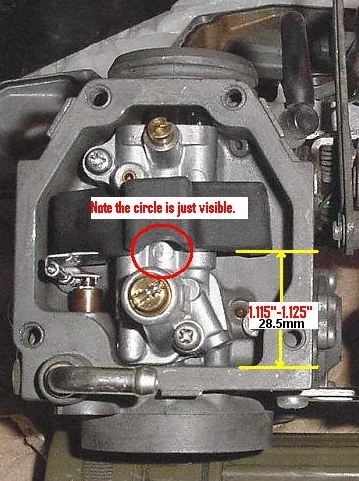
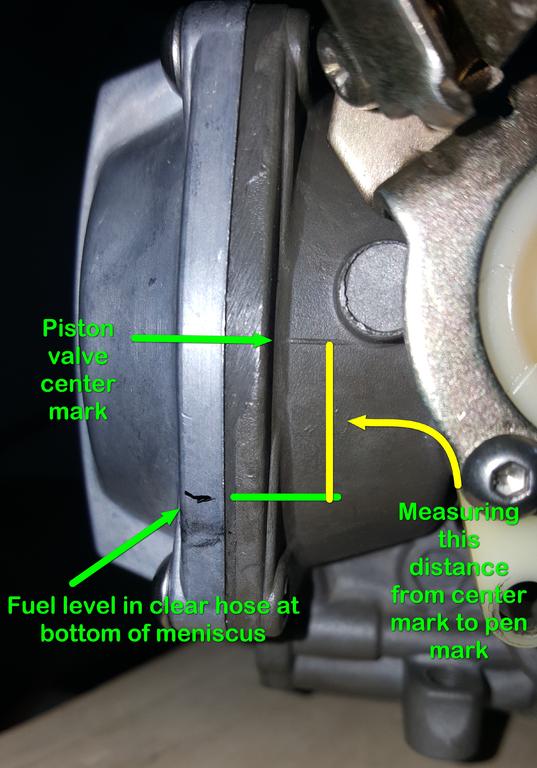
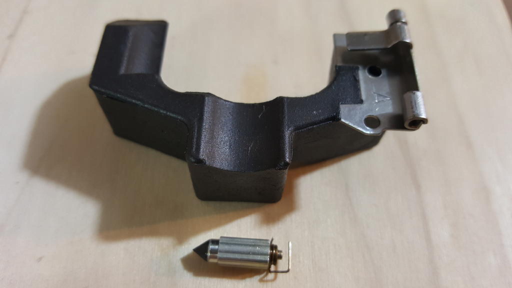
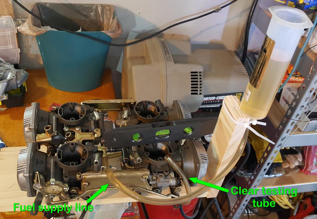
I'm trying to adjust the floats on my '93 Royale and I'm running into problems. I adjusted my floats dry on the bench using this procedure (see pic). Float not compressing the float valve spring. Gap measured on the right side of the float as pictured. I set them all to 28.5mm clearance. I created a wet test setup to test the carbs. I leveled each carb independently before measuring. I let the carb fill with fuel and then drained a little off through the drain valve to ensure the float was working properly. I also tapped the carbs and drain line to ensure there were no bubbles. Then I drained the test line and positioned it directly beside the diaphragm cover and held it firmly in place. I opened the fuel drain screw, let the tube fill, tapped the tube a couple times, and made a mark at the bottom of the meniscus. I measured with calipers from the fuel level mark to the piston valve center mark. Even after testing each carb twice, this 28.5mm dry float setting left me with high gaps (low fuel heights) of 21.3mm, 18.6mm, 17.7mm, and 18.1mm. The manual says 15.5mm to 16.5mm is correct. I split the carbs apart and started to adjust the float height on carb #1 (the 21.3mm gap). After adjusting and wet testing carb #1 twice, I'm running out of tang adjustment. The setting pictured here still only gives me a 17.2mm gap. When I do push down on the float, the float contacts the jet block before the float needle spring is completely compressed. (I can only compress the spring about halfway in this current setting.) I think the tang would almost be touching the float body or the float would contact the jet block before I could get it adjusted to the point that it would give me a 15.5mm fuel gap. See this pic: The bike has 40K miles on it, and the float and float valve appear to be in good shape. The carbs have been thoroughly scrubbed and the float valve orifices are clean. I'm the second owner. Do these look like standard parts? If the float valve were failing, I would expect it to let in more fuel than desired rather than less. Also, if the float were losing its buoyancy, I'd expect to get more fuel than desired, not less. It's as if I have a super buoyant float that wants to close the float valve much sooner than desired, and I'm running out of adjustment on the tang to stop the valve from closing so soon. Or, the float valve is too long and is closing too soon, despite having adjusted the tang down as far as possible. What do you suggest I do next to get this float adjusted properly?

-
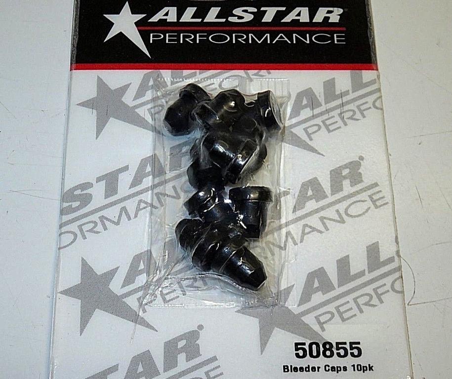
My original rubber bleeder caps finally bit the dust. I also noticed I had no caps on any of the grease zerk fittings under the bike. I can recommend the Allstar 50855 for both. https://www.amazon.com/gp/product/B009Q76TVW/. They're long enough to easily cover the brake bleeders. They're also long enough to cover the short grease zerk fittings all the way over the wrench flats on the zerk. They're a tight fit and take quite a bit of effort to get on or off.
-
Thanks, Kevin. Great pictures! I followed that method to set the floats while dry. I'd now like to do a wet test while I have the carbs off the bike. The pressurized fuel concept is what's currently intriguing me.
-
I've consumed a dozen or so threads about bench testing the carb floats by adding fuel. A few just add fuel without any pressure and a few seem to imply that fuel should be introduced under pressure in the same way that the fuel pump introduces fuel under pressure. When the carbs are connected to the bike, the fuel pump applies some amount of fuel pressure while filling the bowls. I suspect this would affect the amount of fuel the float and float needle allow into the bowl. In other words, some amount of pressure can overcome the float buoyancy and needle pressure, which would force a bit more fuel into the bowl before the needle closed. That's in contrast to introducing fuel with no pressure during a bench test where the float and float needle might block the needle port faster because it's not fighting against any fuel pressure. In order to accurately bench test float levels, should I introduce fuel with a little bit of pressure?
-
89 VR Mix Screws
Bob K. replied to uhfradarwill's topic in Venture and Venture Royale Tech Talk ('83 - '93)
Here ya go: https://www.venturerider.org/forum/showthread.php?112729-How-to-access-idle-screw. That post calls them "idle screws" but they're offiically called pilot screws. If yours are still covered with the brass plugs, drill a little hole in the plug, tap it with a screw, and pull the plug out. -
Thanks, Jeff! That did it. To get them off, I: Cleaned the forks above the joint with 0000 steel wool. Sprayed some WD40 on the joint to lube for removal. I couldn't just twist or pull them off from the top--they seemed to be stuck in place--so I used a long screwdriver and hammer to lightly tap the collar from the bottom. After a couple taps, they came loose and could be removed by hand. Used my fingernail and a small screwdriver to remove the snap ring. Checked the 2 o-rings inside the air joint.
-
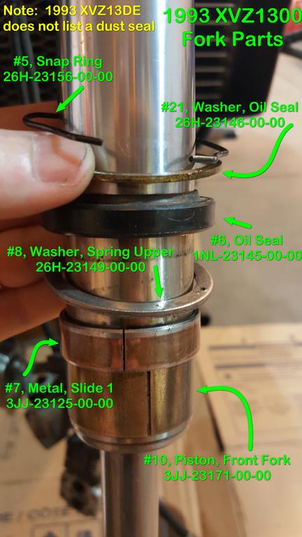
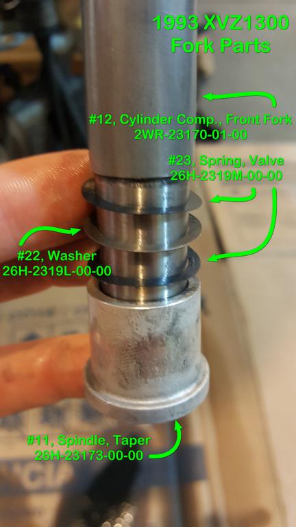
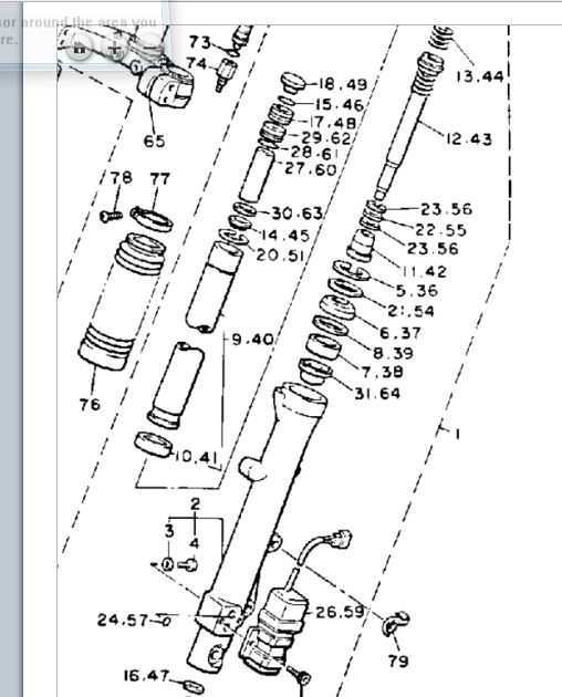
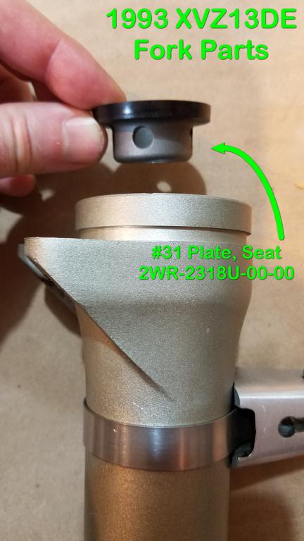
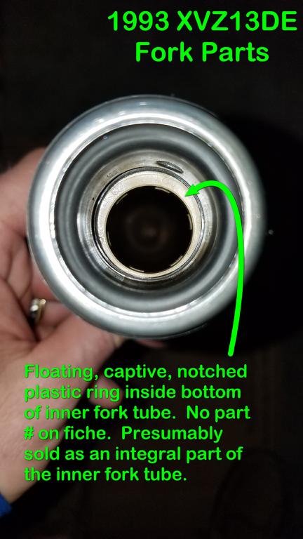
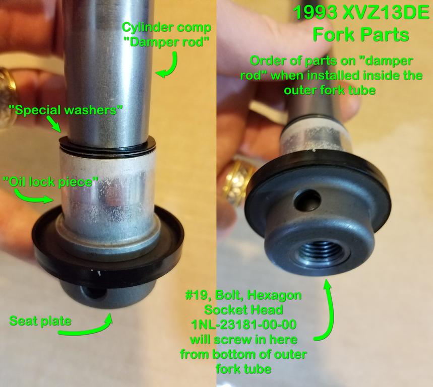
Here are a few pictures of fork parts on my 1993 Royale in order of assembly. The pictures include the official fiche names and part numbers. I hope this might help others who are trying to find the official part names and part numbers when performing fork maintenance. If I have any incorrect IDs, please holler and I'll fix it. Parts on the inner fork. The oil seal washer (referred to as the "seal spacer" in the service manual) was installed with the rounded side (smooth side with rounded edges) against the top of the oil seal. The upper spring washer (also referred to as the "seal spacer" in the service manual) was installed with the flat side (the side with sharp edges) against the bottom of the oil seal. The metal slide (referred to as the "slide bush" in the service manual) and front fork piston (referred to as the "guide bush" in the service manual) appeared consistent and not dependent on a particular installation direction. Inspect the floating, captive plastic ring at the bottom of the inner fork tube. There is no fiche part listed for this, so I suspect it is sold as a unit with the inner fork tube. Parts on the front fork cylinder comp. The service manual refers to this as the "damper rod". The service manual refers to the wavy washers--valve springs--as "special washers". The service manual refers to the taper spindle as the "oil lock piece". The seat plate is the last removable component at the bottom of the outer fork. It goes in first before any additional re-assembly. If you could see inside the outer fork tube after the "damper rod" and related parts were re-assembled and installed, this is how it would look: The numbers correspond with the fiche from https://www.partshark.com/oemparts/a/yam/50043596f8700209bc78be67/front-fork
-
Fork seal rebuild
Bob K. replied to CrazyHorse's topic in Venture and Venture Royale Tech Talk ('83 - '93)
My seat plates fell out as well, but the rubber seal around the top is still in good shape. Do you have any techniques for re-installation? Is it just a matter of fishing it into the bottom of the fork and gently pressing it into place with a broom handle or something similar? -
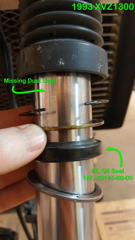
On my '93, I appear to be missing the fork dust seals that go on top of the spring clip. I have fork boots and these boots completely cover everything once installed. The PO may have installed the fork boots and removed the dust seals (if there's supposed to be one on a '93). Interestingly, I see the oil seal (#6) but I don't see the dust seal mentioned on Partshark. I found the dust seal in the fiche for 1989 and previous model years. https://www.partshark.com/oemparts/a/yam/50043596f8700209bc78be67/front-fork# If I have fork boots, do I need a dust seal on a '93? Would it be prudent to install one? If so, what item is it on the fiche?
-
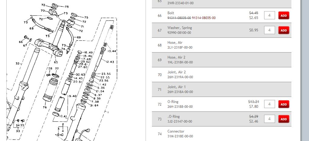
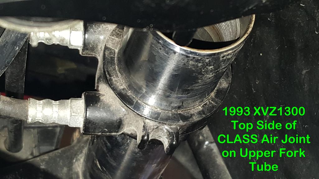
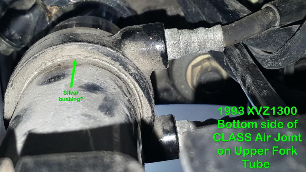
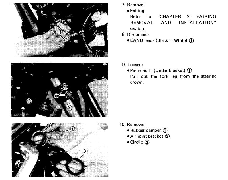
I need to remove the upper (inner?) forks from the triple tree on my '93 to check for bends. I've read threads that talk about the CLASS air joint being held in place on the tube either by snap rings, circlips, or o-rings. The Partshark fiche shows o-rings. However, I don't seem to have any of these. Here's the parts fiche from Partshark. I have the gasket (#75) but I don't have the o-rings (#72). The service manual just says "Remove air joint bracket" with an almost indistinguishable black and white picture. (Gee, thanks Yamaha.) It also says to disconnect the EAND anti-dive leads. (Why?) Here's what the top of the CLASS air joint looks like on my '93. Here's what the bottom of the CLASS air joint looks like on my '93. It looks like there might be a silver bushing/shim underneath the black air joint collar where the green arrow is pointing. How do I get the CLASS air joint off of the upper fork?
-
When I removed the air box and rubber boots from the carbs on my '93, the boots seemed to have a small amount of sealant where they connected to the bottom of the air box. The sealant seemed to be peeling away from age. I couldn't tell if this was OEM or if it was added by the previous owner. If my air box boots are still quite pliable and fit tightly, do I need to seal them with silicone or some other kind of sealant when I re-install them into the bottom of the air box?
-
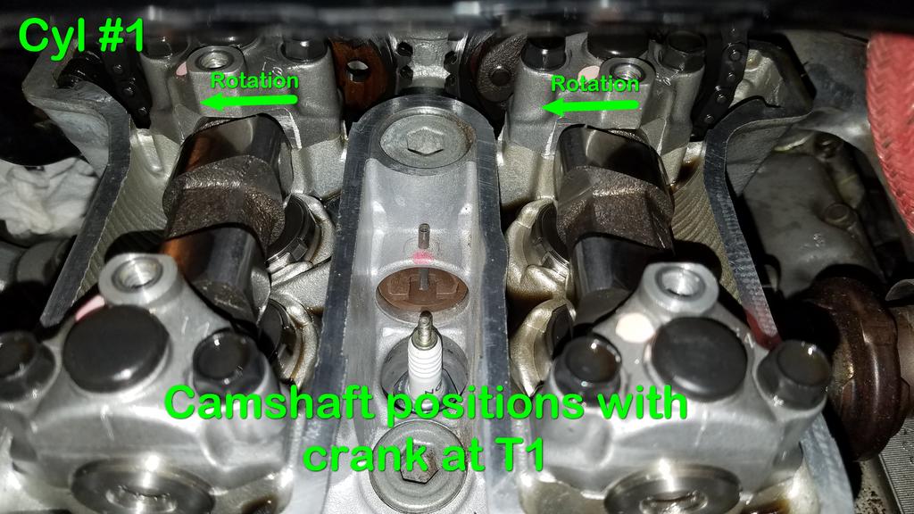
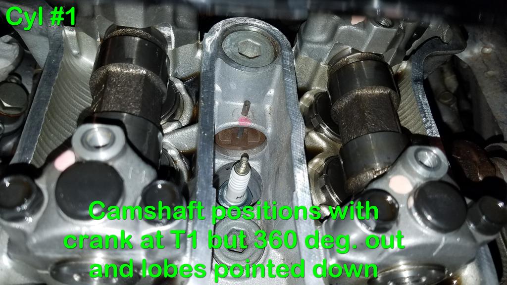
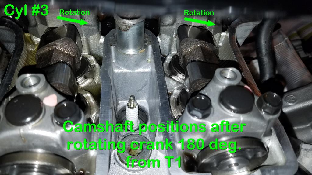
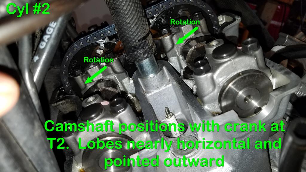
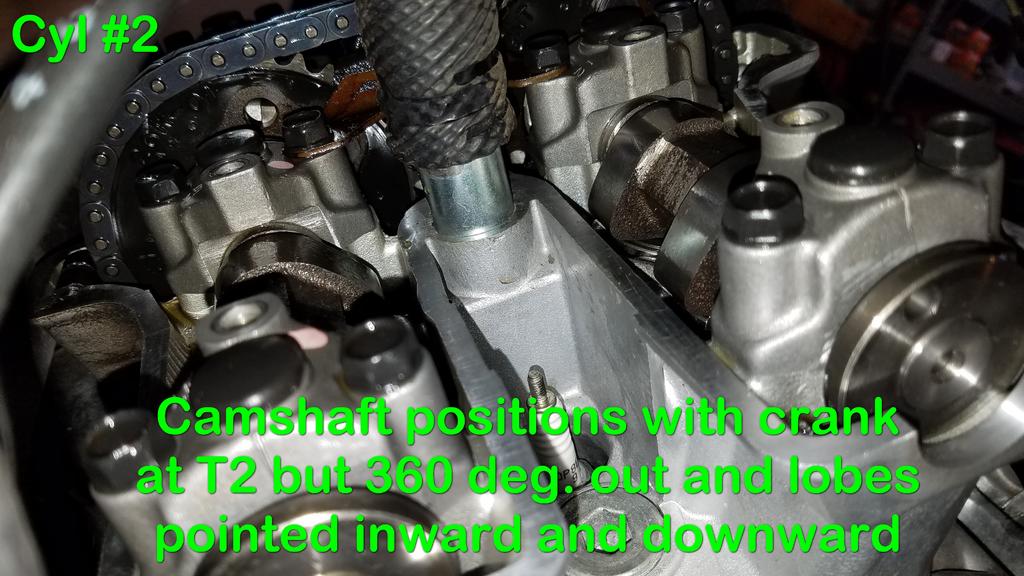
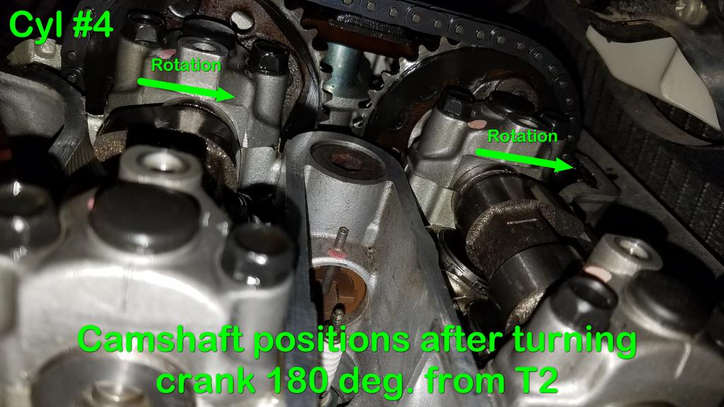
Here are pictures that I took of the camshaft and lobe positions while following Yamaha's method of indexing off of T1 and T2 on the crank. This picture shows the position of Cylinder #1 camshafts with the crank at T1. The lobes are pointed inward and upward. This pictures shows the position of Cylinder #1 camshafts with the crank at T1 when the crank is 360 degrees out and the cylinder is not at TDC at the start the combustion cycle. Notice that the lobes are pointed downward. The exhaust valves are almost closed and the intake valves have started to open. This is not the correct position to start at T1 and begin alignment for Cylinder #1 . O.k. Assume we're back at the correct crank rotation. This picture shows the position of Cylinder #3 camshafts after the crank has been rotated 180 degrees from T1. This is the position to measure Cylinder #3 valves. Notice the lobes are pointed inward and upward much like Cylinder #1 . This picture shows the position of Cylinder #2 camshafts after rotating the crank 180 degrees plus an additional 70 degrees from the measuring position for Cylinder #3 , and aligning with T2 on the crank. Notice the lobes are almost horizontal and are pointed outward from the center. This pictures shows the position of Cylinder #2 camshafts with the crank at T2 when the crank is 360 degrees out and the cylinder is not at TDC at the start the combustion cycle. Notice that the lobes are pointed downward and inward. The exhaust valves are almost closed and the intake valves have started to open. This is not the correct position to start at T2 and begin alignment for Cylinder #2. O.k. Assume we were back at the correct measuring position for Cylinder #2. This picture shows the position of Cylinder #4 camshafts with the crank rotated an additional 180 degrees from the measuring position for Cylinder #2. Notice the lobes are almost horizontal and pointed outward, much like the lobes for Cylinder #2. The correct rotation steps, then, are: 1. Align to the correct T1 position for Cylinder #1. Measure Cylinder #1. 2. Turn the crank 180 degrees. Measure Cylinder #3. 3. Turn the crank to T2, which ends up being 180 degrees plus an additional 70 degrees. Measure Cylinder #2. 4. Turn the crank 180 degrees. Measure Cylinder #4. I note that the lobes are in different positions for Cylinders #1 & #3 (pointed upward and inward) than they are for Cylinders #2 & #4 (almost horizontal and pointed outward). If the official Yamaha instructions have us measuring at different points on the base radius of the lobes--Cylinders #1 & #3 more on the bottom of the lobe and Cylinders #2 & #4 more on the side of the lobe--that would seem to indicate that it's acceptable to measure anywhere on the base radius of the lobes. That includes skipping the official measuring method and just turning the crank on each cylinder until the lobes are pointed straight up (as others have suggested).
-
Carb Setup suggestions
Bob K. replied to dkaiser's topic in Venture and Venture Royale Tech Talk ('83 - '93)
Good! I did indeed inspect and clean the coasting enrichment circuit. -
Carb Setup suggestions
Bob K. replied to dkaiser's topic in Venture and Venture Royale Tech Talk ('83 - '93)
What are the "air bypass diaphragms" you mention? Do you mean something associated with either the starter plunger or the coasting enrichment diaphragm (under the small, round cover)? I just finished disassembling and cleaning the carbs on my '93 and want to make sure I didn't miss something.