dingy
-
Posts
5,403 -
Joined
-
Last visited
Content Type
Profiles
Forums
Gallery
Events
Store
Everything posted by dingy
-
 You did just fine PM'ing me, If you would send another with your email typed in it though it would help me to help you !!! Gary
 -
PM me an email an I will email you cam timing from 83-85 Venture service manual, maybe it will help. Gary
-
Attached separate detail pictures for the front and rear heads showing the cap locations. Gary
-
COP (coil over plug) ignition
dingy replied to Rosie1965's topic in Venture and Venture Royale Tech Talk ('83 - '93)
Picture of the top of the CBR Denso coils I am using. Positive wire is on right side, connector is towards top of picture. Polarity is important. Other picture is what coil looks like, viewed with air box removed, this is left front coil. Object in upper right of 2nd picture is the VBoost servo motor, in case you are wondering what that is. Gary -
COP (coil over plug) ignition
dingy replied to Rosie1965's topic in Venture and Venture Royale Tech Talk ('83 - '93)
Auto, which is what I am using, or Short. Gary -
What I have done to see if valves are seated after I reassemble head is to put plugs in head tight. Set head upside down on bench, level as possible. Then fill combustion chamber area with liquid, I have used gasoline, but then I am an idiot some say, and see if leaks through valves. You want a thin liquid, not an oil. Head gaskets are normally three layers. If you had blown gasket it would be fairly obvious I would think> almost has to blow into water jacket. Very rare to hear of this happening on a Venture, happens a little more often in VMax motors, which are very similar. Gary
-
Note that front cam setup differs from rear setup. I attached service manual PDF of cam install pages only. Doesn't matter for cams, but post what year your bike is when you ask questions, often helps as answer may vary somewhat on year. If you become a full member you can post it in your display header. Gary 1986-1993-Yamaha Venture Cam install.pdf
-
The 1st gen indicator plate appears to be a fit for the 2nd gen motor. With the plate installed, it would be a matter of running wires to front end and installing LED's to indicate gear position. I have mounted 3 LED's on Tweety to indicate 1,3 & 5 gears, that way I don't have to focus on dash to read digital readout. Didn't do 2 or 4th, no LED lit and I am in 2 or 4th, which is very easy to know which I am in. Stock neutral light indicator covers neutral. Gary
-
SaberWing has Narcolepsy!
dingy replied to StormRaven's topic in Venture and Venture Royale Tech Talk ('83 - '93)
Fixed it. The CMU dying in neutral is curious though. The gear indicator circuit are a ground activated trigger, they pickup a ground path through the shift drum as it rotates for each position. There is nothing at the drum different about the neutral circuit. Where the neutral circuit differs is that it is tied to the diode assembly. Inside of the diode assembly there are two diodes, one is in the neutral light, the other is in the side stand relay circuit. A failure of either of these diodes will cause erratic symptoms. Mike said that he had no neutral light in the 5th post, this seems like it has to be caused by the neutral light not having 12v+ on it. Does not address turn signal relation to problem though. Most of the affected circuits run through the 20 amp signal fuse. This doesn't explain the apparent symptom of the cluster dying when the engine stop switch is off though. The thermostat dropping out is indicative of it not being a ground issue causing the overall event. The thermostat gauge has an independent ground circuit that runs through the thermistor in the cooling joint assembly, this ground is totally independent of any grounds directly in the cluster. Not saying it is not somehow tied in the harness to the cluster head ground though. Brakes causing cluster to die could be related to a loose or dirty contact in the cluster. The brake circuit does run through the CMU, but only thing I am aware that it does is to activate the reed switch that disables CMU warning of a brake light failure. The brake light circuit does not seem to need a ground in CMU to allow pass through of current to brake lights. Granted the warning icon circuit on CMU would activate with a bad ground, but with CMU dead, this would not be indicated. Have fun, electrical problems are very hard to diagnose when you are at the bike, let alone on the other side of an internet connection. Gary -
SaberWing has Narcolepsy!
dingy replied to StormRaven's topic in Venture and Venture Royale Tech Talk ('83 - '93)
That color text is hard to read !! Gary -
SaberWing has Narcolepsy!
dingy replied to StormRaven's topic in Venture and Venture Royale Tech Talk ('83 - '93)
The motor dying in neutral is curious though. The gear indicator circuit are a ground activated trigger, they pickup a ground path through the shift drum as it rotates for each position. There is nothing at the drum different about the neutral circuit. Where the neutral circuit differs is that it is tied to the diode assembly. Inside of the diode assembly there are two diodes, one is in the neutral light, the other is in the side stand relay circuit. A failure of either of these diodes will cause erratic symptoms. Mike said that he had no neutral light in the 5th post, this seems like it has to be caused by the neutral light not having 12v+ on it. Does not address turn signal relation to problem though. Most of the affected circuits run through the 20 amp signal fuse. This doesn't explain the apparent symptom of the cluster dying when the engine stop switch is off though. The thermostat dropping out is indicative of it not being a ground issue causing the overall event. The thermostat gauge has an independent ground circuit that runs through the thermistor in the cooling joint assembly, this ground is totally independent of any grounds directly in the cluster. Not saying it is not somehow tied in the harness to the cluster head ground though. Brakes causing cluster to die could be related to a loose or dirty contact in the cluster. The brake circuit does run through the CMU, but only thing I am aware that it does is to activate the reed switch that disables CMU warning of a brake light failure. The brake light circuit does not seem to need a ground in CMU to allow pass through of current to brake lights. Granted the warning icon circuit on CMU would activate with a bad ground, but with CMU dead, this would not be indicated. Have fun, electrical problems are very hard to diagnose when you are at the bike, let alone on the other side of an internet connection. Gary -
No tattoo's at this point, and after the Marines, a decade on the railroad and a several occasions where alcohol was involved, I think it ain't going to happen now. The Hybrid is going to be named Sylvester, all black. Goes well with Tweety. Gary http://i1007.photobucket.com/albums/af193/gdingy101/Tweet_zps06d856a4.jpg
-
Ebay Brake Discs
dingy replied to Midicat's topic in Venture and Venture Royale Tech Talk ('83 - '93)
Put the wave rotors on Tweety this morning. Fit up very nicely. One picture of the FJR rotors I took off, might use them on the Hybrid. Gary -
Do you have link where you found picture so I could get a higher resolution copy of it? Gary
-
Ebay Brake Discs
dingy replied to Midicat's topic in Venture and Venture Royale Tech Talk ('83 - '93)
I have a pair that haven't been put on Tweety yet, got them a couple of weeks ago. The quality looks very good. Shipping was faster than what was expected. http://www.ebay.com/itm/261173291742?ssPageName=STRK:MEWNX:IT&_trksid=p3984.m1439.l2649 Note that these are for a VMax and not a Venture. Gary -
There is no physical difference in the block up through the air box in an 83-93 V4. Venture 83-85 carbs are smaller venturi's, but same mounting dimensions. If it fits an 87 it will fit rest the of them. Gary
-
Rather than an electric pump I carry a CO2 inflator & extra cartridges. It's a lot smaller than a compressor. MC tires take about 2 cartridges to inflate a flat. Also carry a tire plug kit. Gary
-
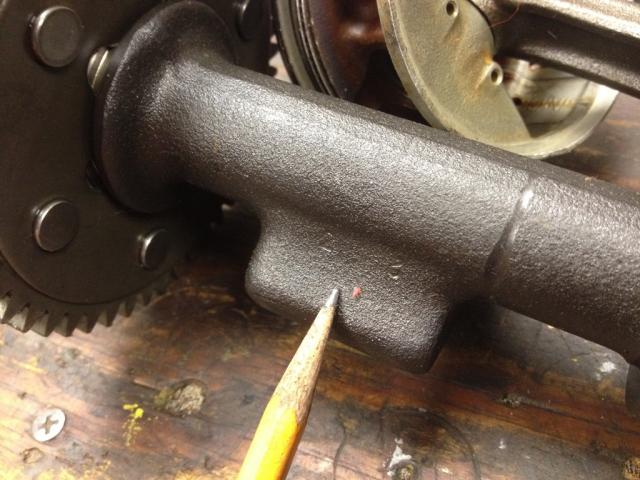
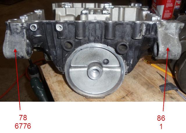
Bearing sizing has been corrected in this post, see thread 13 for clarification. Gary I gave you wrong info in 5th post above, I looked at engine video & am correcting it here & I will edit that post. Error was in case numbers engraved in block. Only the numbers on left side are needed for bearings, upper 2 numbers are balancer shaft, lower 4 numbers are crank mains. I don't know what right to numbers are for. Numbers shown below are what they appear to read to me looking at picture. 1st line in 1st & 2nd group are case numbers. 2nd line is numbers on crank & balance shaft 3rd line is subtracting 2nd line from 1st line and it is number of bearing needed for that journal. 3rd group is showing 7's on rods, I am guessing 4th rod is a 7 as all rods I have seen are 7's and rods shown in video are all 7's. Rods are easier to machine than crank or shafts so they will tend to be more consistent. rods. Both journals on crank appear to be '3', there are 4 rods so you need 4 sets of bearings. Therefore all 3's in the crank rod row. Subtract 2nd line from 1st line and it is number of bearing needed All bearing sizes are read facing front of motor, left to right. Case/Mains 6 5 5 6 Crank/Mains - 2 3 3 3 Main Bearings 4 2 2 3 Left out Brown (size #3) on Outer Left main (J1) - Black (size #2) on Inner Left main (J2) - Black (size #2) on Inner Right main(J3) - Green (size #4) on Outer Right main (J4) Case/Balancer 7 6 balancer - 2 2 Balancer Bearings 5 4 Green (size #4) on Left balance (J5) - Yellow (size #5) on right balance(J6) Rods 7 7 7 7 Crank Rods - 3 3 3 3 Rod bearings 4 4 4 4 Numbers don't line up right when I post this so you will have to mentally line them up. I attached a screen capture of numbers formatted better. Gary
-
I know what you meant Eck, just laughed when I read it. Gary
-
Pictures attached of clear side covers Tweety got. Water pump is cool when it has green coolant in it. Some of other covers are not on motor in pictures, like water jacket plug covers. Pegs not on etc. Gary
-
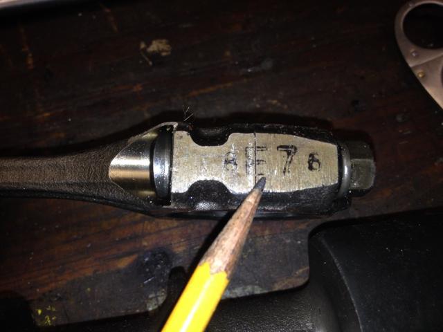
Picture attached of numbers on balancer shaft & rod. E7 is number that is important. Easier to send pictures here than to reply to your PM, can't attach pictures in PM. Gary

-
Goldwings are special, my bike doesn't have a passenger side. Or a drivers side for that matter. I set in front,passenger in rear. Gary
-
There are numbers engraved on the lower crankcase, 2 digits over 4 digits on one side and 2 on other. Left side lower 4 digits are crank main bearing size, upper 2 digits are balencer shaft sizes. Don't know what right side numbers are for. On the crank, there is a 4 digit number stamped on it and a 2 digit number, and a 2 digit number on the balancer shaft. Each rod will have a number on it, usually ink stamped on, not stamped or engraved, I think each starts with an 'E', but not always. Letter doesn't matter, only number. The case & rod numbers are 8 to 5 range, the balance & crank shaft are 0 to 4 range. subtract the shaft numbers from the case numbers to get the bearing sizes. See attached PDF cut from service manual, and a picture of bearing markings on case. Most bearings are in mid range, #'s 4 & 5. That is design tolerance factory tried to hit. Plastigage is a real chore on the block, Block halves need to be reassembled with sealer, then split to read plastigage. You need a known size bearing in place, so you know which way to go if reading is incorrect. Then do it again. Rod bearings, are much easier to plastigage. Almost all motors I have torn down have had color markings unreadable on bearing s. There is a thin strip on edge, in middle of arc on one side of bearing. The videos that are available for $20 for VMax motor, go into bearing selection in depth. Gary 82448.pdf [ATTACH=CONFIG]105715[/ATTACH] [ATTACH=CONFIG]105716[/ATTACH]
-
COP (coil over plug) ignition
dingy replied to Rosie1965's topic in Venture and Venture Royale Tech Talk ('83 - '93)
The COP's connect to the 2 pin connector on the main harness at each coil. Cop's do not make a connection directly to TCI. There are 4 yellow plugs (2) pin plugs, 1 to each coil, stock coil has mating plug. Unplug stock coils and wire COPs into the harness end of each plug. Gary -
COP (coil over plug) ignition
dingy replied to Rosie1965's topic in Venture and Venture Royale Tech Talk ('83 - '93)
It's about 30 min or less to install ignitech TCI. Then remove stock plug wires to coils. Install cop sticks and wire power leads into connectors where existing coils plug into main harness. Probably a couple hours installing COP's. Ignitech TCI does not connect directly to coils, it interfaces through existing main harness via a short adapter cable. Changing to COP's from stock coils is seperate change from Ignitech swap. Benefit I see with Ignitech, there is no need for resistors being installed in COP's. Ignitech has a setting that is changed when using lower primary resistance coils. Gary