Leaderboard


Popular Content
Showing content with the highest reputation on 05/10/2021 in all areas
-
Hey Tom, It is my belief that at least two pistons on the right front caliper are "frozen" and are no longer pushing the pads against the rotor. The 2 pistons are usually on the side opposite the Banjo Bolt. The right front brake lever ONLY controls the right front caliper! If you want to have BOTH front calipers engage, you must use the foot pedal as well. The intent of the De-Link Kit is to allow you to use BOTH front brake calipers when you use the right front brake lever, and engage the rear brake when you use the foot pedal. The De-Link Kit IN NO WAY effects the Anti-Dive Valves on the MKII Ventures. (1986 to 1993) Plus on the MKI Ventures, (1983 to 1985) the De-Link Kit comes with all new S.S. replacement Anti-Dive Lines! I am not sure if you are aware of this or not, but when you installed the Progressive Fork Springs on your bike, you nullified the action of the Electric Anti-Dives anyway. The original design of the Electric Anti-Dives was to redirect the fluid flow during a "panic stop" situation by slowing the flow of fluid from the bottom of the fork tubes to the top of the fork tubes by activating a valve which is connected to the front brake lever. The Progressive Fork Springs do the same thing Mechanically. As the Progressives compress, the spring rate becomes stiffer and slows the compression of the fork tubes. (This is the same thing the Anti-Dives do!) My suggestion would be to rebuild your 34 year old right front caliper, at a minimum! But even if you rebuilt ALL three calipers and Master Cylinders, you would STILL have 1980's VINTAGE brakes on an 800 pound Motorcycle! Here are the results of the testing I did before I offered the De-Link Kit to the members of this forum. I took my 1987 Venture Royale with excellent STOCK brakes on it and ran the bike up to 60 MPH and stopped the bike as quickly as I could without crashing. I did this MANY times, measured the results, and came up with an average stopping distance. I then installed the De-Link Kit and a set of R1 Front Brake Calipers, which now allowed BOTH front calipers to be controlled by the brake lever, and did the same procedure all over again. The De-Link/R1 brake set up stopped 16 FEET SHORTER, and it was much easier to control because I had equal braking force of BOTH Sides of the front wheel. Even if you are an expert rider with linked brakes, THE FACT REMAINS that the left front brake caliper has smaller pistons than the right front. This is a FACT, period. You would need to have a superhero amount of "brake feel" to engage the right front brake caliper with the brake lever, and match that braking force with a caliper of a different size with the foot pedal in a panic stop situation and keep the bike stopping in a straight line. Now there are a very small group of riders that have absolutely NO reason to worry about upgrading their braking system. These "riders" chug around in 5th gear at 40 MPH, don't lean their bikes over at all, EVER, and most likely have a non-functional left front caliper and a dragging rear caliper that has turned the rear rotor blue. Their brake fluid looks like Coke-a-Cola, and they have NEVER looked into their rear master cylinder, ever. They paid $100.00 for their bikes, and this is the most money they have ever spent on it during the entire time they have owned it. I'm sorry, but these people are not RIDERS, they just own equipment. Even if you don't buy the kit I offer, invest some time (and money) in your braking system! Ebay, Amazon, and Facebook Marketplace are ALL excellent sources for good quality used parts to make your braking system better and SAFER. And Safety, my friends is the KEY word here. If you have questions, please feel free to ask! Earl4 points
-
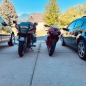
Just expressing my appreciation for freshness, did a little brake maintenance this morning then out for a borderline sweaty ride, came home, did laundry and made Mother’s Day wifey some grilled shrimp and steak. Cleaned up, took a nice hot shower and into fresh washed jammies and sheets. Windows open with crisp spring mountain air, and a tasty nightcap. More often it’s the little things that make the most out of life.3 points
-
When using automotive oils you need to be aware of what additives may be added to the oil. Some of these are not clutch friendly.2 points
-
You need to look at the SAE circle on the back of the bottle and if it says energy conserving at the bottom of the circle dont use it on bikes that share motor oil with clutchs.1 point
-
I need to move! Too much urban noise here for me to sleep with open windows. Guess that is why I so enjoy my back country canoe trips. Despite the hard work of paddling and portaging I always come home refreshed from sleeping outdoors and grabbing an early morning swim in chemical free water before starting each day.1 point
-
That sounds so refreshing. Glad you had a great day.1 point
-
I had just posted on another Venture site that I see some of the 2nd gens and RSTD occasionally when out on rides. But I can say I have seen no 3rd gen new styles.1 point
-
Submitted by Bill Anton If this is something you may need to do (Sunday or Monday when bike shops are closed) print the procedure and put it in your owners manual. DISASSEMBLY PROCEDURE ===================== NOTE: This info is specific to the 1983-1993 Yamaha Venture motorcycle. Make intelligent (safe) changes for other motorcycles. Included in the procedure are REASSEMBLY torque specifications. The size listed is for the socket or wrench, not the bolt thread size. Initial tools required: - ratchet - 3" extension - sockets: 12mm, 14mm, 19mm - 14mm box-end wrench (if you loosen/remove the final drive) - 27mm flat wrench (rear axel nut) - 6mm Allen wrench (front axel pinch bolt) - pliers (for cotter key) OR get a get a 5/32" $0.75 hitch pin clip (Lowes / Home Depot) and never have to hassle with the archaic cotter key again - tie-down strap(s) - carpet / cardboard (for under forks) !! IMPORTANT: Control the bike's weight balance to make it safe to work around. You may have to ADD some WEIGHT to the REAR of the bike (saddlebags & trunk) BEFORE starting the procedure, so the front of the bike doesn't fall when the front wheel is removed in step 13. You should REMOVE everything from the saddlebags & trunk AFTER the front wheel is removed so the rear of the bike doesn't fall while working on the rear wheel. 1. Put the bike on the centerstand. 2. Connect tie-down straps from the bottom of the centerstand legs, to the engine guards. Pull them as snug as practical. 3. To keep the fork tubes from getting damaged in step 10, place a cardboard or carpet (from a car?) under the front tire area. 4. Loosen the right muffler-to-exhaust clamping bolt - 12mm. REASSEMBLY - Torque 14 ft-lbs. 5. Remove the right muffler mounting bolt - 14mm, and remove the muffler. REASSEMBLY - Torque 18 ft-lbs. 6. Remove the rear brake caliper - 2, 12mm bolts. REASSEMBLY - Torque 32 ft-lbs. TIP: Use axel wrench flat end to spread the brake pads during reassemble. 7. Loosen (not remove) the rear axel pinch bolt - 12mm. REASSEMBLY - Torque 14 ft-lbs. TIP: If the cotter key is aligned vertical, file marks on the pinch bolt end of the axel for easier future alignment. If it isn't aligned vertical, make the marks when you have the axel out. 8. Remove the rear axle nut and washer - 27mm flat wrench. *** DO NOT REMOVE THE REAR AXEL NOW *** REASSEMBLY - Torque 110 ft-lbs. TIP: Replace the cotter key with a 5/32" hitch pin (Lowes / Home Depot). 9. Front wheel remove: 1. Remove both brake calipers (2 bolts each) - 12mm. REASSEMBLY - Torque 32 ft-lb TIP: Get 2 pieces of cardboard 4"x4" and fold them in half and insert them between the pads to hold them apart TIP: Use axel wrench flat end to spread brake pads during reassemble. 2. Loosen the front axel pinch bolt - 6mm Allen wrench. REASSEMBLY - Torque 14 ft-lb 3. Remove the front axel bolt - 19mm. REASSEMBLY - Torque 75 ft-lb 4. Remove the front wheel. TIP: When you pull the wheel out, the speedo cable and drive will fall away -- don't worry unless you are over a dirt surface. REMINDER: On reassembly the speedo housing top-tab goes into the fork notch. 10. Carefully lower the front of the bike until the fork tubes are on the cardboard or carpet. 1. Start slowly pulling down on the fairing near the mirrors 2. As the pull-down becomes easier, slide one hand under the fairing for support 3. Squat a little as the fairing gets lower 4. As the weight increases, bring the other hand down for more support ****** REMOVE WEIGHT from the saddlebags & trunk for better counter balance. 11. Remove the rear axle. Notice the caliper bracket washer, it goes between the bracket and the swingarm. 12. Remove the brake caliper bracket. 13. Remove the 4 final drive attaching nuts - 14mm. then reattach one lower nut 1 1/2 turns so the drive shaft can't pull out of the U-joint and waste a lot of time to put it back together. REASSEMBLY - Torque 30 ft-lb 14. Pull the final drive rearward until it is against the nut. This gives a little more clearance to get the tire past the final drive. CAUTION: The wheel and tire weigh about 42 pounds. Be prepared for step 15. 15. Pull the wheel away from the final drive, and out of the swing arm. 16. Roll the rear wheel out under the fender and do what you removed it for. *-*-*-*-*-*-*-*-*-*-*-*-*-*-*-*-*-*-*-*-*-*-*-*-*-*-*-*-*-*-*-*-*-*-*-*-* Removal of the final drive unit at this point is recommended to lube the driveshaft splines (Molybdenum Disulfide Grease) as long as the wheel is off anyway. See the FINAL DRIVE REMOVAL procedure below. *-*-*-*-*-*-*-*-*-*-*-*-*-*-*-*-*-*-*-*-*-*-*-*-*-*-*-*-*-*-*-*-*-*-*-*-* 17. Reverse the DISASSEMBLY procedures from 14 to 1. - in step 10, do the sub-steps in 3-2-1 order. ---------------------------------------------------------------------- FINAL DRIVE REMOVAL PROCEDURE (optional) ============================= 1. Remove the 4 final drive attaching nuts - 14mm. REASSEMBLY - Torque 30 ft-lbs. 2. Pull the final drive out of the swingarm. NOTE on 86-93 models: The driveshaft oil seal makes the shaft "stick" to the final drive. The driveshaft can be pulled out with a firm force. DO NOT lube 86-93 driveshaft rear splines, final drive fluid lubes them. BE CAREFUL if you pull the shaft out of the final drive, oil can drain from the final drive. FINAL DRIVE REASSEMBLY PROCEDURE ================================ 1. Reinstall the driveshaft: 1. Pull (hard on 86-93 models) the driveshaft out of the final drive. Set the drive aside, being careful to keep it tilted up to prevent fluid loss. 2. Put the transmission in neutral. 3. Use a flashlight, and insert the driveshaft into the swingarm, and use it to align the U-joint so that the yoke is vertical (12 & 6 O'clock), and angled down toward the bottom of the swingarm. 4. Put the transmission in gear (so the U-joint can't turn). 5. Reattach the driveshaft to the final drive. 6. Insert the driveshaft into the swingarm, letting the front end drag on the bottom of the swingarm. 7. Wiggle the wheel mating gear on the final drive to mate the driveshaft with the U-joint - then put the 4 nuts on http://www.venturerider.org/firstgenwheel/Rear%20wheel%20removal%20-%201%20Kneeling%20position%20-%20rear%20view%20(Small).JPG http://www.venturerider.org/firstgenwheel/Rear%20wheel%20removal%20-%202%20Kneeling%20position%20-%20side%20view%20(Small).JPG http://www.venturerider.org/firstgenwheel/Rear%20wheel%20removal%20-%203%20Kneeling%20position%20-%20front%20side%20view%20(Small).JPG http://www.venturerider.org/firstgenwheel/Rear%20wheel%20removal%20-%204%20Kneeling%20front%20view%20(Small).JPG http://www.venturerider.org/firstgenwheel/Rear%20wheel%20removal%20-%205%20Parts%20removed%20in%2010%20minutes%20(Small).JPG http://www.venturerider.org/firstgenwheel/Rear%20wheel%20removal%20-%206%20Centerstand%20tie-down%20strap%20(Small).JPG http://www.venturerider.org/firstgenwheel/Rear%20wheel%20removal%20-%207%20Wheel%20out%201%20(Small).JPG http://www.venturerider.org/firstgenwheel/Rear%20wheel%20removal%20-%208%20Worms-eye%20view%20of%20rear%20wheel%20well%20(Small).JPG http://www.venturerider.org/firstgenwheel/Rear%20wheel%20removal%20-%209%20Rear%20brake%20caliper%20bracket%20position%20pin%20(Small).JPG1 point