Search the Community
Showing results for tags 'relay'.
-
I was in to the relays when the starter switch stuck, dose any one have some relay boots the want to let loose of ? They are broken all but one or may be know some where I might get some. Probably not good for them to just hang there. Thanks, Dale
-
Like many here, I wanted more than the stock horns could give me. I decided to install the Stebel. I didn't really like mounting it where the stock horn is. I decided to mount it on the left rear, under the trunk and behind the HD lights. I made a bracket out of some aluminum bar I had and used a 'P' clamp and plastic ties. Not a lot of clearance for the bag lid and fender, but enough. That was the main reason for some plastic ties, to hold it away from things. Definitely louder than stock, but not as loud as I was expecting. While I felt better about being able to make some noise, I still didn't have what I wanted. I was thinking about another Stebel, but I saw some 132 db horns at AutoZone and I decided to give them a try. What I bought were Blazer Horn's Highway Blaster I did some searching but couldn't find much on them. A search on 'Highway Blaster Horn' turned up some Freeway Blaster horns that look just like these and in the same db range (125 - 130) and price ($15-$20 each). I bought a high tone and low tone. They are mirror images so I could mount one on each side of the bike and still have the 'bell' as far forward and out of the way as possible. I mounted them behind the lower fairings. The bell sits on the front crash bar. The included bracket goes from a stud and nut in the center of the horn to the lower bolt that holds the air filter housing. The horn bracket is thin and I placed it between the housing and the housing bracket. I soldered two wires into the wire from my relay to the Stebel and ran them under the tank. You can just see the relay in a shot of the right side. It sits on top of the fluid reservoir under the right side cover. Two wires (white in the pic) are spliced into the stock horn below and activate the relay when the horn button is pressed. One red wire is fused to the battery and the other side of the relay goes to the three horns I installed. I used a plastic tie to hold the relay in place. Now when I hit the horn button, I have 5 horns going off (2 stock, Stebel, 2 Blasters). First time I tapped the button, I flinched. By flinch, I mean I closed my eyes, shook my head, and took a step back. Tapped it again and all the grandkids came out to see what was going on. Even though they knew it was coming, they flinched every time I tapped the button. My wife finally made me stop. She was afraid the neighbors would get mad. I'm loud enough now.
-
OK I'm not an electrician. I can't read them lil squidly lines on blueprints. I would like to know how to hook up my new to me horns. I have a 30 amp relay I got at Autozone . Iwant to hook up thru my existing horn wiring if possible using it to fire the relay and the relay to fire both new horns. The rely has numbers on it that I know correspond to which wires I hook up. Am I making sense? The horns are stebal electric with 2 connectors so I'm assuming they are not self grounding. In other words what wire goes to 86 what to 85 and ect.? Sorry to be so dense.
-
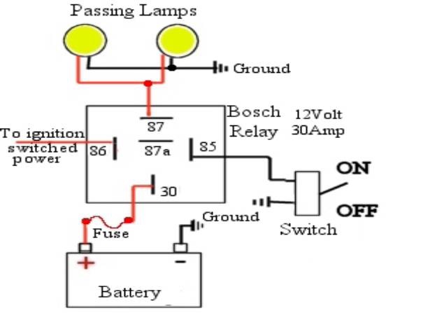
I've read this so many times I can't see it any more. Typos and questions: I'll be glad to correct/explain as needed. How to make your passing lamps modulate when the horn is activated. If they are not already on they will be turned on while the horn is activated. Some information: Headlight modulation is authorized throughout the US by the DOT. It is wise to carry a copy of the law in case you find a LEO who doesn't know this. You can't legally modulate at night, and all modulation must be synchronized unless you're a LEO. Most Diamond Star modules have a Heads Up mode. This causes the attached lights to flash for three seconds when the horn is honked. I wanted my passing lamps to flash as long as I hold down the horn button. As I was finishing this up (I thought.) I did a final check for parts availability. It turns out Signal Dynamics has changed models and the newest one won't work. Some old Diamond Stars might be available, but I'd definitely call and check the number. Because of this I added the instructions for Kisan modules as well. I have not used the Kisans myself. (See Notes 3 and 4 at the bottom for more info.) Schematics follow at the end of the article. 1 – Using a relay to activate the passing lamps. Lamps installed as per Yamaha instructions. 1 normally open horn relay Wire Female lugs Wire loom material Fuse (inline or mini addon fuse block) Remove seat and tank. Split fairing. Run a wire in wire loom from the battery, up the backbone, through the neck, and into the fairing. Use an inline mini fuse or an addon fuse block. Depending on how much of this mod you want to do you may want to run more than one wire. This is a power wire – 12 or 14 gage. This wire goes to 30 on the relay. Find the wire that's patched into the red/yellow high beam wire. Cut this wire between the switch and the passing lights. Place a female lug on the wire that goes to the headlights and put it on 87 on the relay. Place a female lug on the wire that comes from the switch and put it on 85. Run 86 to ground. If you don't care about the modulation and horns you can use some double stick tape, stick the relay to the bulkhead, and stop here. You'll have your passing light powered from the battery, activated by a relay switched only when the power is on. You've also reduced the load on your headlight circuit. 2 – Add a horn activated modulator. 1 Diamond Star modulator #01014 (Follow DS instructions – red to power, red and white to light.) OR 1 Kisan pathBlazer P115W–H3-HD (Follow K - instructions.) 2 horn relays Wire 2 Piggy back lugs (Radio Shack Quick Disconnect Adapter Set 64-3064) Some female lugs Wire loom material. Double stick tape Remove left lower. Remove tank. Loosen/remove neck plastic. Split fairing. Run two signal wires (16 or 18 gage) in wire loom up from the area of the horn, through the neck, and into the fairing. If you are retaining the stock horn, solder/crimp piggyback lugs to the wires and place on horn. Place plug on piggyback. If you're removing the stock horns use standard male lugs. Put the lugs into the horn plug. Toss the horn. http://s_bumgardner.home.comcast.net/lowerfairing.jpg (horn area of lower) From the front of the bike run the horn signal wires to your right. Give yourself a foot of wire or so to work with and trim, then add a female lug to each wire. In order to keep some of the wiring under control I made a harness for the relay set. I used double stick tape to stick the relays together side by side, then placed lugs on each 85 and 86. I routed the wires that go to the front connectors toward the back next to the other wire. Once everything was in place I crimped the lugs onto the wires, and wrapped the wire sets with electrical tape in strategic spots. I put male lugs on the ends of the two wires. http://s_bumgardner.home.comcast.net/relays.jpg (Relays and wiring harness) Plug the two male lugs from the relay harness into the females on the horn signal wires. First relay – doesn't matter which. DS - Cut the toggle switch off of the modulator, leaving the wire. Solder a female lug to each wire. Hook these to 30 and 87a. K – Cut the red wire on the light sensor wire set and splice in enough signal wire to reach the relay. Solder a female lug to each new wire. Hook these to 30 and 87. Cut your passing lamp power wire between its switching device (switch or relay) and the lamps. Install the Diamond Star or pathBlazer module on this wire as per its instructions. Decision time: Do you want the lights to flash at night? Technically this is probably illegal. The main headlight may not modulate after dark. Period. These however are passing/auxiliary lamps flashing when you honk the horn. Their use presupposes an emergency wherein I want the clown about to run me over to notice I'm there and change his mind. I don't care how the DOT feels about it. If you decide to have them flash at night you need to: DS - cut the sensor off, then solder the wires together and insulate the end, then tape it out of the way. K - mount the sensor where it receives light from the headlight. The pathBlazer uses an adjustable sensor, so cutting it off probably won't work. If you want the light to not flash at night follow the standard sensor mounting instructions for each. I mounted the one for my headlight in the plastic piece at the bottom of the fork, toward the back, pointing down. There's room for two. I removed the sensor for the passing lamp modulator. http://s_bumgardner.home.comcast.net/lightsensor.jpg (Sensor placement) Pick a second relay. Splice into the light power wire before the existing switch/relay. Run this wire to 30. Splice into the light power wire after the existing switch/relay and run this wire to 87. http://s_bumgardner.home.comcast.net/relayswired.jpg (Relays - from left: Horn - Headlight modulation - Passing light modulation - Passing light power with horn. Separate - Switched passing lamp power for normal operation.) Use double sided tape to stick the relays and modulators to the bulkhead. If you're doing the horn and/or headlight modulator, save this step for later. http://s_bumgardner.home.comcast.net/relaysinplace.jpg (Relays in place on front right, lower bulkhead) You can stop here, your passing lamps will now flash when you honk the horn. If they are not turned on, the second relay will turn them on while the horn is activated. Power on, test, and button up. 3 - You can add a set of Fiamm Extra Loud electric horns inside the fairing. Just add another relay in parallel with the others (85 and 86), then use this to power the horns. The Fiamms will fit inside the fairing. The supplied mounting brackets must be attached to the radio mounting bracket, one on each side. The brackets must be massaged to get the horns to fit without touching the fairing. I used two of the mounting brackets on each horn to get good strength. One seemed too weak. You may find that the upper bolts yield a better position than the lower bolts. Run a fused wire from the battery to 30 on its relay, then from 87 to both horns. Ground the horns to the radio framework. http://s_bumgardner.home.comcast.net/horns.jpg (Fiamm horns) Parts for this: 1 set of Fiamm Extra Loud electric horns (132 db) 1 horn relay A couple more lugs A bit more wire 4 - You can also add a headlight modulator on the high beam. If you do, add another relay to the horn circuit, same as above. You will need to turn off the headlight modulator when the passing lamps are modulating. DS - Cut the toggle switch off the headlight modulator and add lugs. Put these on 30 and 87. It'll turn off the headlight modulator while the passing lamps are flashing. K – Cut the red wire to the light sensor and add two wires with female lugs on the ends. Route these to 30 and 87a. This will turn off the headlight modulator while the passing lamps are flashing. Parts for that: A Diamond Star module installed to the high beam as per instructions (red to power source, red and white to light). OR A pathBlazer P115W–H3-HD module installed to the high beam as per instructions. 1 horn relay A couple more lugs A little more wire If you didn't stick it all to the bulkhead earlier, now's the time. Power up, test, and button everything up. Note 1: I went to Pep Boys, in the horn department, and found good quality relays for three bucks each. They have both normally open and normally closed terminals. I've found low end relays with 87a cut off. These will work for all but one place on the Diamond Star install. The relays used on lighting systems cost five bucks each and all require a fancy harness and plug to remain fully rigid. Used without the plug these relays can be activated by moving the wires attached to the switch lugs. Note 2: If you get the Fiamms from this place, you'll get a five lug relay and all the rest of the stuff you need to add the horns. Note 3: Any Kisan pathBlazer will probably work for the main headlight. All you need to be able to do is interrupt the signal from the light sensor. I contacted Kisan and a tech there verified that opening the sensor circuit would cause the modulator to return the light to solid operation. That's what we want. Note 4: Newer Diamond Star modulators (#01013) will not work. If it hooks up to a single light and has a switch, and/or light sensor, it should work. Bear in mind that the Diamond Star module # 01014 modulates when the switch is OFF and stays on solid when the switch is ON. The Kisans modulate when ON and stay on solid when OFF. In other words, if it flashes at the wrong time move 87/87a to the other. (Schematics) http://s_bumgardner.home.comcast.net/circuitDScolorFinal.jpg (Diamond Star #01014) http://s_bumgardner.home.comcast.net/circuitKisanColorFinal.jpg (Kisan pathBlazer)
-
I'm hearing that some riders install a "relay" when they upgrade to other passing lamps -- what does a relay do? DREBBIN (the electrically challenged)
-

-
Fiamm Horn Installation You folks know very well that there are usually a number of ways to do a job. I'm not saying that this is the absolute best way of installing these horns but it's the way I did it. If you have suggestions on how to improve on this, please start a discussion in the General Tech area and maybe we can all learn something. That being said...this is my story. Though this installation was done on my second generation Venture, I'm sure that much of the wiring and etc. would apply to the first generation or the Royal Star also. I ordered the chrome horns with the intention of mounting them somewhere on the side of the bike. I just couldn't find a place that I like though so finally decided to just mount them inside the faring. Obviously I would probably not have bought chrome had I known that I was going to just hide them anyway. The first thing you have to do of course is split the faring. If you have never done that, I posted a separate write-up on my procedure for doing it under the Second Generation topic of the Technical Library. Once you are inside the faring, the rest is fairly straight forward. The particular horns came with some chrome straps about 3" long with a hole in each end. As you can see, I utilized holes that were already in the part of the faring frame that holds the speedometer unit. There are two holes there that are not being used. There are rubber pads in the holes but I just popped them out and put them away in case I ever need them. This is a steel frame and is very solid. These horns are actually self grounding through the mounting lug but the bracket that I bolted them to is painted so it was a matter of scraping off the paint or using a ground wire. I decided to use the ground wire. Why create a place for corrosion to start by scraping off the paint. I simply used a piece of #14 wire with ring terminals on both ends. Just under the audio unit on the right side is a ground wire and I just connected two new ones to the same screw...one going to each horn. Now...the horns came with a relay and if you are installing heavy duty horns, you certainly want to use a relay. As you can see, I simply removed one of the screw that holds the audio unit and bolted the relay right to it. Very simple. http://www.venturerider.org/horns/relay.jpg The white wire that you see going to the relay is the main power for the horns. The instructions say to simply run a wire to the battery through an inline fuse that you'll have to purchase elsewhere. There is nothing wrong with that but I didn't have an inline fuse and didn't want to go to the store. After thinking about it, I decided to power it off the same circuit that powers the 12V receptacle. Now if you use the receptacle for heated clothing or other heavy duty items, you will want to do as the instructions say and run a wire to the battery. In my case though, I only use the receptacle to power my IPOD MP3 player and it pulls hardly any amps at all. So...I simple ran the white wire from the relay across to the wire going to the receptacle and spliced it in. If you take this route, you WILL want to go to a bigger fuse on that circuit. The receptacle is fused for 5 amps and they horns call for 10. This fuse is located inside the lower left cowling as indicated by the next picture. http://www.venturerider.org/horns/fuses.jpg They are marked inside the lid of the fuse box so simply remove the 5 amp fuse and replace with a 10 amp. So... you now have main power to the relay and the horn is grounded. All you need to do now is connect the relay to your horn button. So...where the heck do you do that? Well....If you look carefully at the next picture, you will see where I tied into a pink wire. This is the wire that comes off the horn button. It did go into the plastic connector you see just below it but I simply pulled it out of the connector, cut the end off and crimpled it to my wire going to the relay. So now the horn button can trigger the relay and all is great. One note. I had intended to leave the original horns connected as well as the new ones. Due to the circuit feeding back through the original horns though, I found that the new horns would honk when the key was in the accessory position. Rather than mess with isolating them and due to the fact that you can't hear them anyway, I just decided to heck with them. Here are pictures of the left and right sides. http://www.venturerider.org/horns/left.jpg http://www.venturerider.org/horns/right.jpg My opinion of these horns? They are MUCH better than the stock horns. I can assure you that you will be heard when you set these things off. Even still though...I expected a bit more. I mean...if you run up behind somebody and press the horn button...they are going to JUMP...but..they probably won't wet their pants. I wanted them to wet their pants....maybe I expected too much. Anyway, if I had to rate them between 1 and 10...I would probably give them about a 7. If I had it to do over again...I would do so...but if I was putting them in the faring, I would just go with the round plain type...not these chrome models. Don Nelson