Vickersguy
-
Posts
173 -
Joined
-
Last visited
-
Days Won
6
Content Type
Profiles
Forums
Gallery
Events
Store
Everything posted by Vickersguy
-
Help!! I lost a part.
Vickersguy replied to R.h.abbott's topic in Venture and Venture Royale Tech Talk ('83 - '93)
How about this ? https://www.ebay.com/itm/175646334146?epid=1323047448&hash=item28e5565cc2:g:eO0AAOSwuLBjM8m1
-
Help!! I lost a part.
Vickersguy replied to R.h.abbott's topic in Venture and Venture Royale Tech Talk ('83 - '93)
https://www.ebay.com/itm/131688978041?hash=item1ea9465679:g:1VgAAOSwuela34Zi The part is available used. Best i could do you you. -
To defend myself, only slightly, three years ago before I abandoned the bike in the back of the garage I used a color-tune to set the pilot screws. I had some confusion because I could get a blue color across a wide range of turns on the pilot screws, roughly 2 to 4 turns. I guessed roughly three turns, more or less, and had inconclusive results. Honestly, I don't remember going back and fine tuning the pilot screws afterwards. I lost my notes as to where I set them and in the process of redoing the valves and prepping the bike for use, and trying to sort out multiple issues, the pilot screws were overlooked. Their mal-adjustment came back with a bang when I first took the bike out last week. You cannot troubleshoot a bad ignition system if your carbs foul two cylinders in only 12 miles. Tomorrow I will check to see if the adjustments I made tonight have helped. The reason I put the bike up is that not only did it run poorly but the top end was making weird screechy sounds. Really loud and it sounded like something was really off. When I checked the valves this year, the valves were just like I set them and I was looking at the manual checking the conversion from mm to inches, when I spotted that the exhaust valve clearances in the manual were tighter than the intake valves. Really ? Sound right to you ? I will point out again as I did in another thread, THE VALVE CLEARANCES IN THE '83 YAMAHA FACTORY MANUAL ARE IN FACT REVERSED. Anyway, when you are going through a troubleshooting process you must eliminate variables. Messing with multiple widgets at once just muddies the water. The bike runs like garbage. The only sane thing to do is to go back to the beginning and do the check list from square one. Don't skip steps or jump to conclusions. I would go on about adjusting carbs but there must be 100 threads here about adjusting carbs and it would be totally redundant. In the meanwhile I will discuss my deep wisdom on the subject of bleeding brake systems....
-
Ahh... it was #4 carb and I noticed when the bike started pulling towards the right... As this is a TECH forum, I thought I might share a special electrical trick I discovered... If you have no room left in your breaker panel in your garage or if you are sad because your air compressor or welder keeps tripping the breaker, here's how to fix it at almost no cost what so ever !!!! TA DA !!!
-
Note to SELF... A properly tightened main jet looks exactly the same as one gently finger tight, that unscrews and falls to the bottom of the float bowl to jam the float.
-
Before we all get carried away with social commentary and what not, no matter the entertainment value, I am reminded that this is a TECH forum. In the interest of full disclosure I must also note for the record, that I am struggling with carburetor issues as well as the spark issue. The correct vinyl tube has been delivered by the little brown truck of joy, along with the windshield washer repair hose barbs. I made a template that bolts to the carb diaphragm cover with marks to indicate the correct fuel level in the float bowel. I immediately discovered the right rear carb drain hose used to check the float level is damaged and gas poured all over the motor from the hose when I cracked the drain screw open. The right rear carb float appears to be stuck and the carb is flooded. Front two are fine. They gotta come out AGAIN. So right now I will share what little I have discovered from about 6 hours chasing TCI repair across a dozen forums. The blue and white spherical diodes ( 8 ) I was so happy with, may be bad even though they look OK. They should be changed out regardless of how they look. The round cylindrical capacitors, ( 17 ) which are now 40 years old, should be changed out. They are well past their life expectancy even if they look OK. I'm not very happy about that because there are so many. Doing most of the solder joints is not enough. You really have to re-solder them all to be sure. Changing out the 4 big transistors in the heat sinks is a good idea. From what I can find, if you do these 4 things, change out the blue/white diodes, change out the big transistors, replace the "barrel" type capacitors, and re-solder the solder joints, about 80% of the TCI boxes come back on-line. This is do-able. Carbs first. I will come back to this after the float issue is corrected. I found a better pic of damaged blue/white diodes. I also enlarged a pic of the xylol/acetone mix applied to the goo. You can see it wrinkling up the goo under the green capacitor. When it looks like that, it can easily be removed with a toothpick. Any remaining goo can then be wiped away with a q-tip.
-
Good One Ronnie ! I might add... Promote on Social Media the idea that " 0 " miles per hour is still fast.
-
Thank you so much Marcarl, for your kind words. Because I've always believed that too much of a good thing is almost enough, I have contacted my ham radio buddy to see if he has some insight to this spark issue. While I wait for his input, I thought I might find inspiration from the Government to help me in my time of need: My plan going forward... 1) Appoint a diverse commission to study the black box that must include persons with degrees in Horticulture, Philosophy and Art History. They must also come from different countries and have English as a second language. 2) Get a statement from an economist to prove a motorcycle that does not run is better than one that does because the money not spent on gas and insurance improves the household bottom line. 3) Wire together several dead black boxes to increase the amount of sparks I'm not getting. 4) Re-register the motorcycle as " operationally impaired " so I can get a handicap sticker and a rebate on the registration. 5) Go on a diet to see if the bike will become faster when I loose weight. 6) Get my neighbors to push the bike up a hill, then coast down the hill in front of reporters to prove that it's all better now that I fixed it. 7) Go on a visit to foreign countries ( with Tiki Bars and wide beaches ) to study other people with tiny tiny bikinis and their broken motorcycles. 😎 Modify motorcycle performance standards so motorcycles that do not run are as cool as ones that do.
-
Well.... I pushed hard tonight, installed the replacement capacitor and the NPN coil transistors, and did a function test. The good news / bad news. The good news is that I didn't kill the black box. It still functions. The bad news is that the spark, though better, didn't improve as much as I hoped it would. Qualitatively, the spark has gone from 10% of what I wanted to see, to about 25% of what I wanted to see. It clearly is better though the " arc welder " spark I saw seems to be an anomaly. I see a hot spark from time to time, but not consistently. I really wanted to report an awesome victory to impress the one or two people who will see this post, you know, get a ticker tape parade and the key to the city, a statue and so forth. Alas it is not to be ! I have really run out of ideas / options at this point. Far be it from me, not to take this last opportunity to continue beating the subject to death. I do want to warn people who would like to replace bad capacitors, that most of the capacitors on the board are polar. They have a + and a - wire. The board is marked with a + for the + wire. The negative wire will be marked on the body of the capacitor. Just an FYI. My statue will forever rest off in the boonies, far from the Venture Hall of Heros !
-
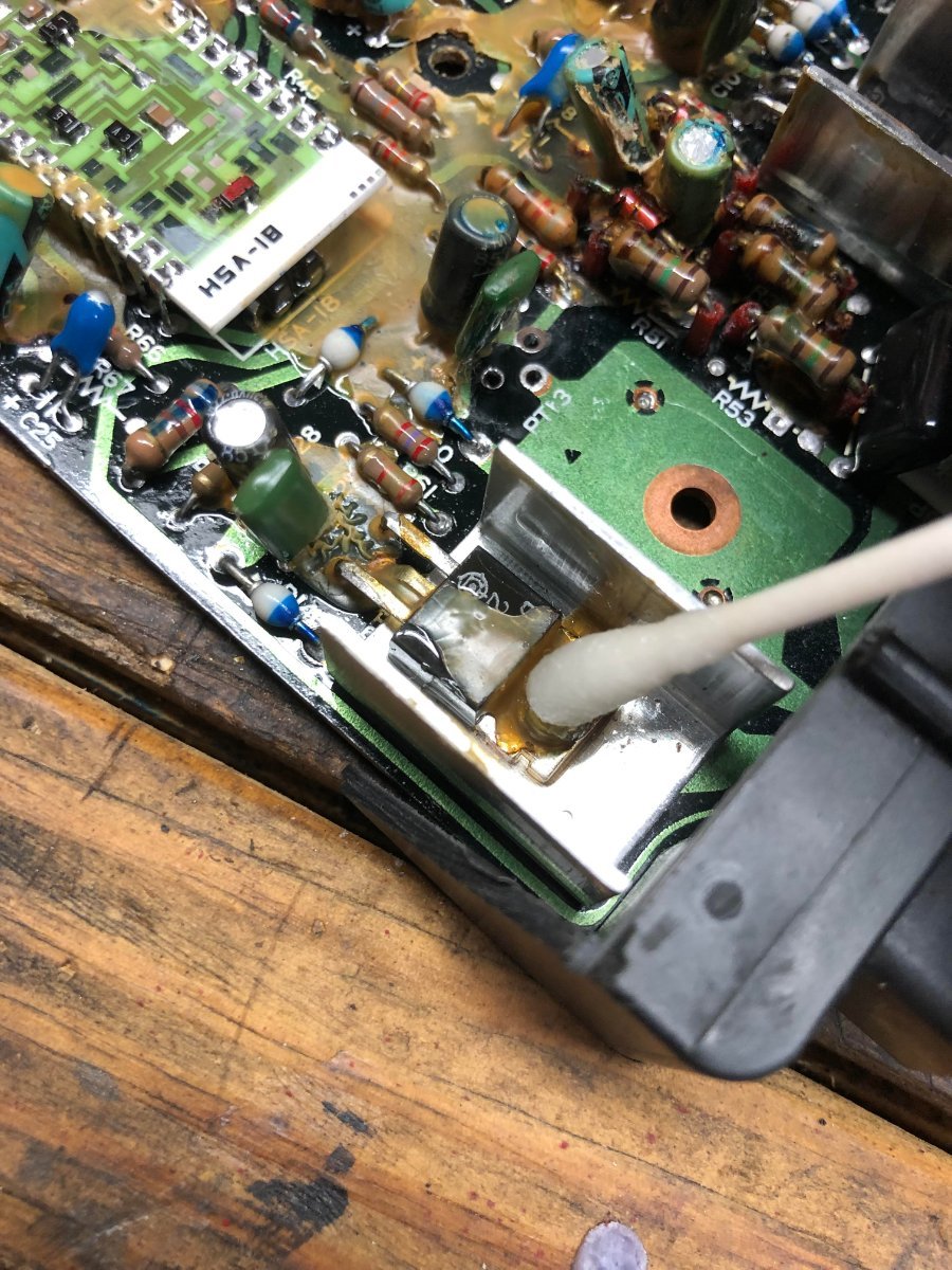
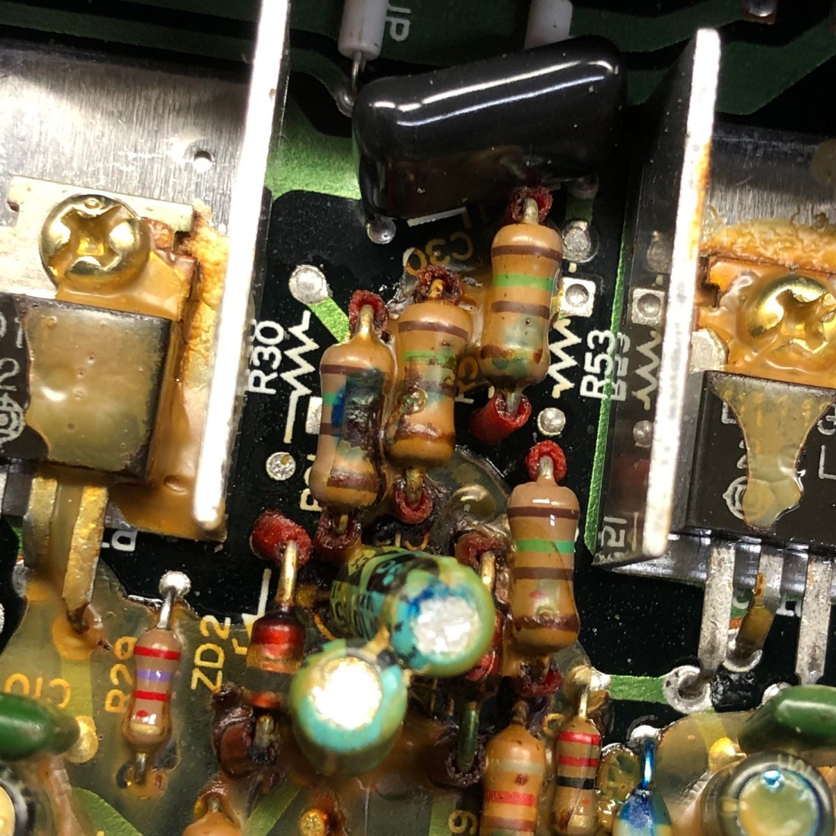
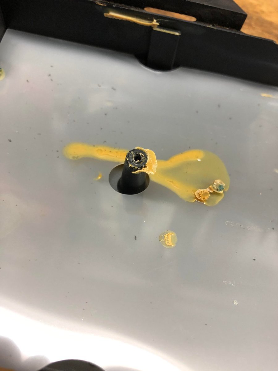
Back to the grind.... It occurs to me I might mention how to deal with the GOO. This brownish goop seems to be randomly poured over the board. I speculate it is to mitigate vibration damage. It probably contributes to over heating components as well. Never the less, it must be removed to repair the board. Can't solder through it. My personal solution was to test some solvent on the glue stuck to the center post in the cover. Non-flammable carb cleaner just bounced off it. As it is a glue I tried acetone and it softened it right up. Acetone evaporates too quickly and is unsuitable as a softening agent because of it's quick evaporation rate. So I mixed it 50/50 with xylol a solvent with a slow evaporation rate to hold the acetone on the part. This worked out quite well. I apply the mixture to the area to be cleaned with a Q-tip. While it is softening I break off the sharp tip of a toothpick and then use the blunt end to break up and move the goo off whatever I'm cleaning. Then I go back with a fresh Q-tip and wipe it all clean. This has worked very well.
-
Hey Saddlebum, don't discount being cheap and stubborn. I have an '86 in my back yard if you find you need some parts... Free parts ? Yeah, but you have to pay shipping.
-
Aside from the blue/white diodes that turn to powder, the only other part on the boards that can be visually identified as being is a failure mode, are the capacitors. Electrolytic capacitors have some identifying characteristics in failure. These are swelling and rupture. If you take a close look at the "top" or "end" of the capacitor you will spot a place where there is a small X etched into the aluminum. I will do my best to show this in a pic. If there is corrosion or the 'X" has broken open or split, this indicates over heating and insulation failure inside the capacitor. Bumps, swelling of the case and traces of "goo" from the bottom are also signs of failure. Here are two pics, one of the two bad capacitors I found and a detail of one of the capacitors after I removed it. The sides of a capacitor should be smooth as a tiny coke can. This one looks like a aqua egg roll. Not good.
-
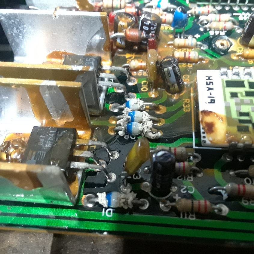
I have never heard of the transistors failing on the Venture forums. However I have read that they fail on the Virago forums. We use the same transistors in our boards that they use in the Viragos. I'm changing mine out because I can, they are cheap, and there is a difference between the spark on the plugs. This might be explained by a failure mode in these transistors. Here is a link to the replacement bits: https://www.digikey.com/en/products/detail/stmicroelectronics/ST901T/1039285 The transistor in the upper right has been replaced and to one in the lower left is ready to be soldered in.
-
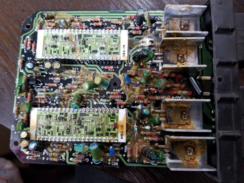
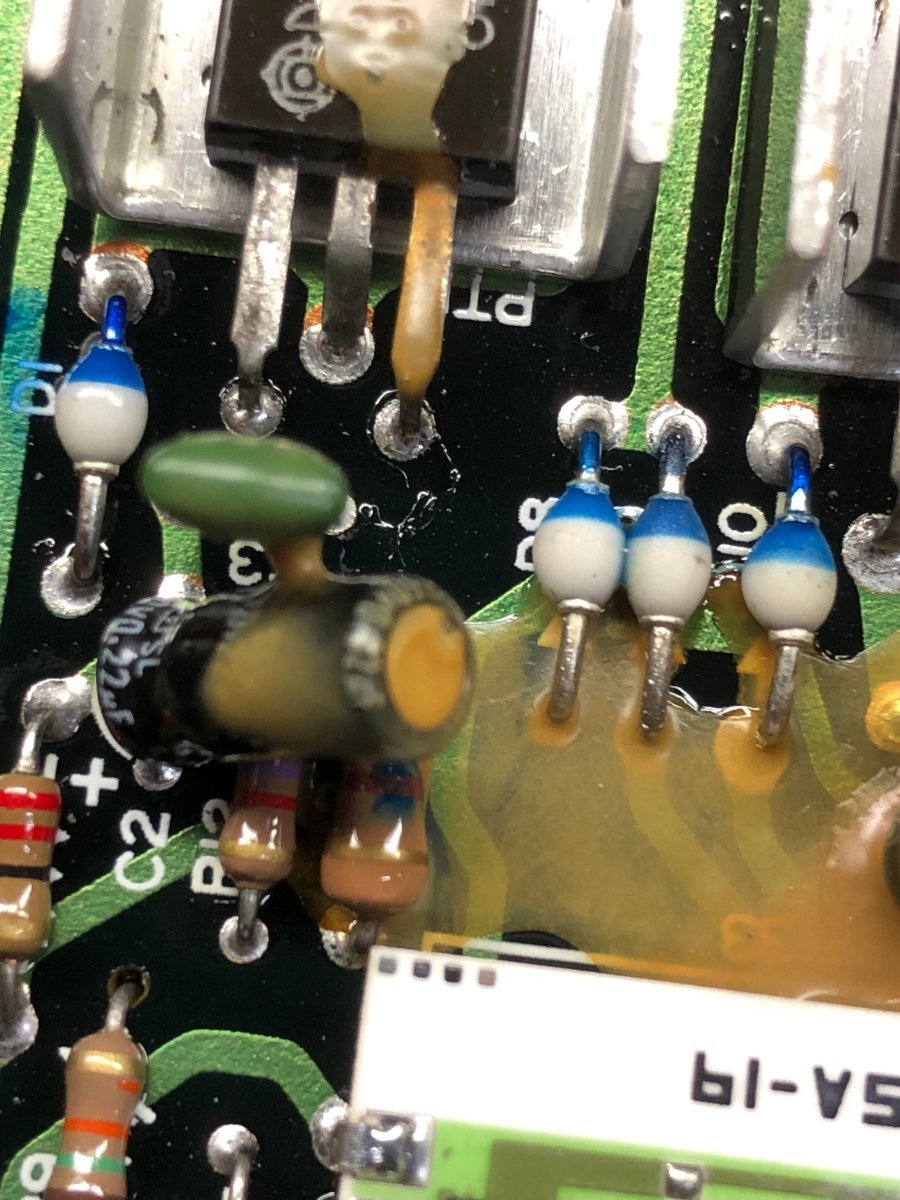
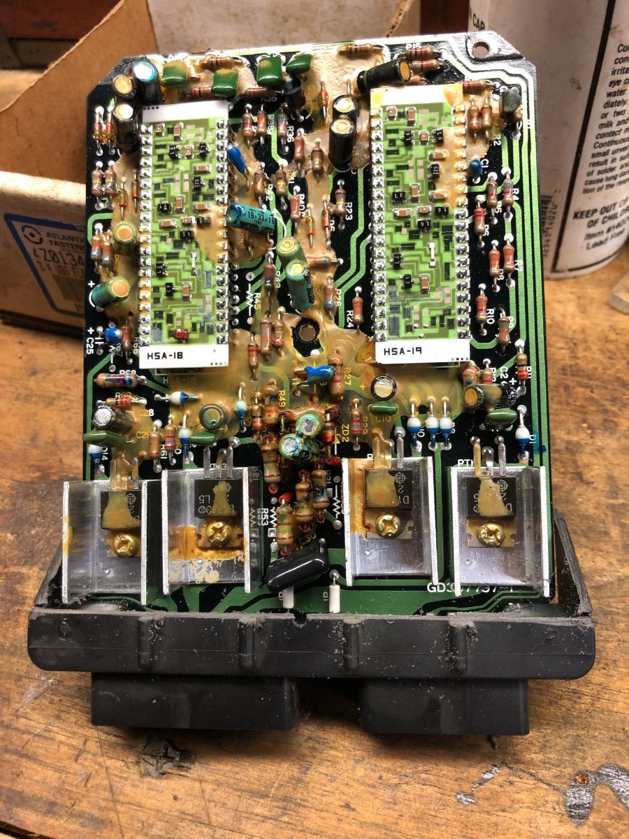
Next is a visual inspection of the board. I cannot tell you much about the architecture of the board but I will tell you what I think I know. The two large sub-boards ( HSA-18 and HSA-19 ) I have been told are to do with the advance curve. They cannot be replaced or repaired. Do not damage them. There are small black squares on these with laser cuts in them. They are carbon resistors printed on the boards. Even a small scratch in these will destroy them, so be careful. The large bits in the aluminum heat sinks are the transistors that ground the coils to produce spark. You should inspect the solder joints on this side as well. There are copper traces on this side as well. This is complicated by the goo slopped all over the place. There are two known places that fail on these boards. The first point of failure are the 8 blue and white diodes. You can see 4 of them above the two transistor heat sink assembly on the lower right side of the board in the previous post. Three are side by side with another just to the right. When they are in a failure condition, they typically start to fall apart and turn into powder. If these totally fail, they will destroy the whole board. Mine look minty and totally intact. I will not be replacing them at this time. Here is a pic with powdered diodes and a pic of my good diodes. You will have to enlarge the pic with the bad diodes to see them well.
-
The next step will be to remove the cover you have just cut loose. There are FIVE screws holding the circuit board to the box. There is one screw in each corner and do not forget the one in the center of the board. ( You can see it in the picture in post #7 ) You will have to gently pry the corners free with a small flat blade screwdriver. The center screw may be held to the board with some glue. It will break free if you gently and repeatedly stress the glue joint. This is what you get.
-
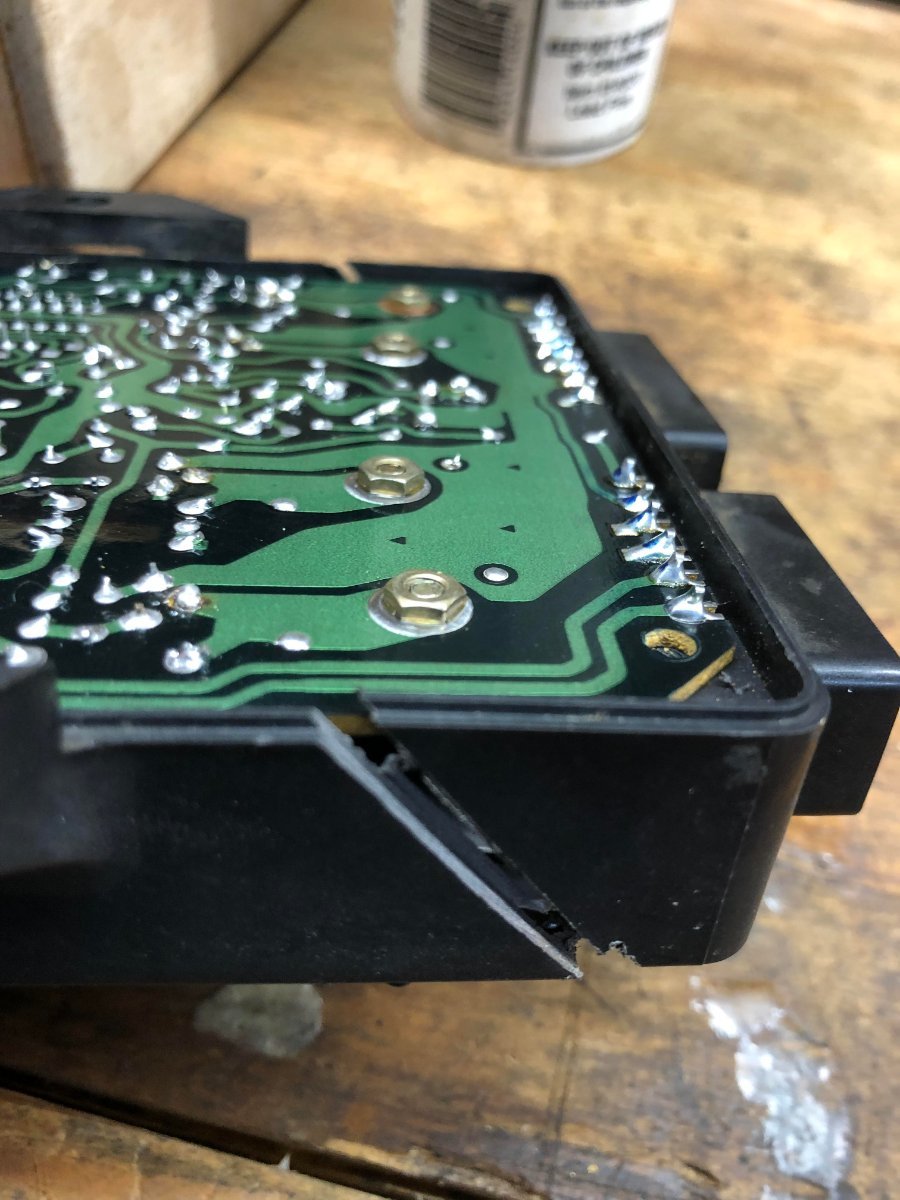
Partial victory is, upon reflection, no victory at all. The spark has improved slightly on two cylinders and that's not good enough. So based on absolutely no expertise what so ever and with wishful thinking my greatest ally, I will continue this thread that I am utterly unqualified to write. I think that is the point. Success is unlikely but even failure is instructive. If by some wild circumstance I should succeed, awesome ! So I will continue to prattle on. First issue is how to open the other side of the box. I opted to cut it at an angle to increase the length of the glue joint and reduce leverage on the glue from stresses. I will probably repair the joint with fiberglass and epoxy after the box is proven functional.
-
I have a partial victory ! Left Rear and Right Front cylinders are back on line with a spark that would do justice to an arc welder ! Right rear and left front are 100% better but still weak, no longer reddish but still wispy. Will check the board again.
-
I forgot I had a pic of some bad joints. I'll post them just to help folks who don't know what they look like. You can spot them by the grey circles in the solder. I have marked them with yellow. Not all of them just a few so you can see what they look like.
-
Next step is to put the bike back together. You will not be returning the black box to it's former location anyway, you will be securing it to the top of the air cleaner. Don't let the plugs get buried, but put it all back together. As you re-solder the joints, test your box from time to time. You may have fixed it and not even know it if you don't test it. Do all this before you cut up the box to remove the other side. I was not clear in the previous post. The bad joints will be exposed with the removal of just the one cover...
-
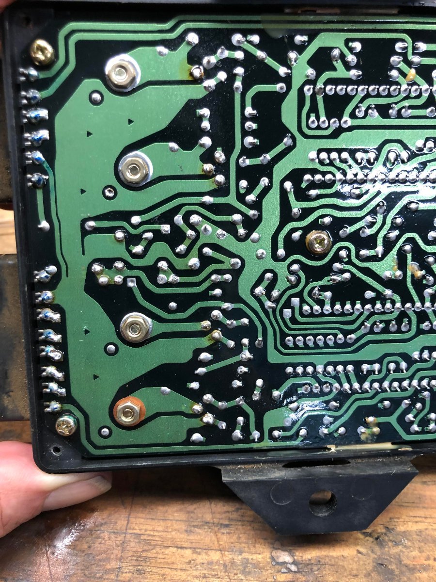
Oh Kee Do Kee. I worked overtime in an effort to restore my old pic posting skills. I hope I got it right. As they say, "Pics, or it didn't happen". After my success with the Yamaha instrument control panel and being filled with delusions of adequacy, I pulled the black box. For those unmotivated to research the process, let me assure you that it is quite a chore. Some tips that may help. Of course you have to pull off the fairing. 1) pull the battery box and air box to get room. 2) pull the four bolts that secure the coil mount frame and tilt that up to get access to the Phillips head screws that hold the black box. 3) DO NOT try to loosen them with something short like a Phillips head impact bit. They have been there for FORTY YEARS. Squeeze in a tiny set of vice grips ( the 4 inch ones ) to crack them loose before you put a shorty Phillips on them or you will go thru Heck to remove them. OK. Now the easiest part. Take off the four screws in the corner and pry open the box... Here's what you got... The four nuts hold down the "drive" transistors that ground the coils to produce the spark. The row of solder joints on the left connect the plug spade pins to the board. In order to remove the board from the box those would have to be de-soldered. The easy bypass for that is to cut the box away as you will see in later pics. What the point of this is, is to expose the bad solder joints. Aged solder joints will crack and are the source of the problems with the class system and the instrument panel malfunctions. I see no reason they are not a problem on this board as well. It could be that all that is required is to re-solder these connections. I am not going to go through a description of " cold solder joints ", or this post will be 16 pages long. Sufficient to say I found two dozen is just a few minutes.
-
never mind, it worked...
-
Did my best, followed the instructions, no sign of any e-mail address on my profile. Email deleted by Freebird.
-
Hey Saddlebum, yes, and also cleaned the connector plug for the pick up coils! It is 100%. There is also a thread that is of interest, in a generic way, giving an overview of sorts to the rebuilding task. https://xjcd.org/node/1537
-
Finished the last checks. The electrical system, outside the black box, is fine. Good voltage, good grounds, 1.6 ohms resistance from the + battery lead to the input of the box. I have 9 coils to work with and they all ohm out the same plus/minus an ohm or two. Bike idles like a dream but once the situation in the cylinder changes everything goes sideways. Next, I have to get out the box. I think I want a zipper on the fairing for this nonsense. I have the diodes and power npn transistors ( ST901T ) en route. A fading spark could mean a bad capacitor. I may be changing out some if I can find replacements. I don't know if I can check caps with an oscilloscope. Have to check with my ham radio electrical buddy. Here's a link to the data the XJ yamaha guys dug up on their black boxes that used the same transistor we have in the early Venture boxes. https://www.xjcd.org/TCI_transistors
-
Replacement power transistor is ST901T
.png.f407d00fbc792eb3f9af709c03c17ac4.png)

.png.f4b5b38666132413ff78a8c965ed11c0.png)

.jpg.41c0293f725d4e865822ab7cc07648ac.jpg)

.jpg.151de81ea1f22ba490fa80d6034148dd.jpg)
FRM.jpg.6593403d9c7f6797c5b950fed86be53f.jpg)