


Flyinfool
-
Posts
13,152 -
Joined
-
Last visited
-
Days Won
7
Content Type
Profiles
Forums
Gallery
Events
Store
Posts posted by Flyinfool
-
-
Just had my 3 month checkup with the Cardiologist.
He said that things are working as expected. My tuner is pacing 91% of the time. I did have one full blown episode of AFib in the last 3 months but that is much better than the every other week that was doing. There was also 2 episodes of unexplained high heart rate that never went to irregular rhythm of AFib. The Doc said that was most likely my heart trying to go into AFib but the tuner was filling in the blanks so that I did not go irregular. He said that is exactly how it is supposed to work.
All of the other questions and concerns that I had were answered as being perfectly normal and to be expected.
He did make the comment that some day when I do die, it is very unlikely that it will be because of my heart. But he did say that I should still lose some more weight......
 When's dinner.........
 -
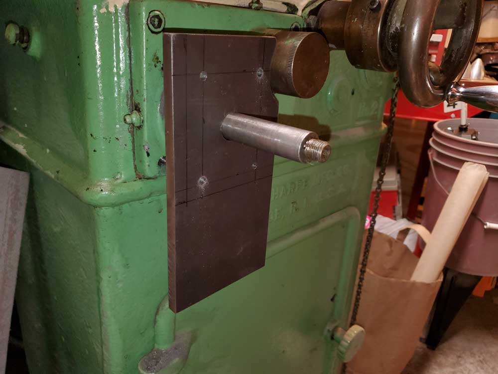
Well the chips have started flying.
I started by drilling a shaft size hole in a plate that will eventually become the mounting plate for the motor and belt drive. I then added the 4 mounting holes that will attach the plate to the machine. I drilled those mounting holes with a #7 drill which is the tap drill size for a 1/4-20 tapped hole. I then slid this plate onto the machine and used it as a drill bushing to drill the 4 #7 holes into the cast iron of the machine. I will later enlarge all of the holes in the plate and make them into slots so that I can later move the plate to adjust belt tension. I have also tapped the holes in the machine.
LOTS more work left to do. But at least I have started.
-
It sure looks like a Marks, someone must have assumed it was stainless and just bolted it it up without painting it first.
-
IT WORKS!!!!
I now have all of the electronics assembled and playing well together. The reversing switches actually make the motor go the other way, on command even.
Now I get to start figuring out how to attach all of this to the grinder.
-
Weeelllllll
It is just a tiny little motor, about a 2 inch cube (57mm cube), and it was only turning about 1.5 RPM, so plenty of time to let go. I do not have a proper setup to measure torque other than my fingers.
Today I hope to finish that final interface. Then I get to start designing the mechanics to attach the motor to the grinder. Then I get to start making the parts to make it happen.
-
After more testing, I found that I can get the motor down to about 1.5 RPM. with a 3/4 inch dia timing pulley mounted on the shaft I can not stop it just by trying to hold it. I was impressed at the felt torque from this tiny NEMA 23 x 57mm unipolar motor being run as a bipolar on 24VDC.
Interestingly another feature of stepper motors is that the slower they are turning, the greater the torque. Highest torque is when powered but not turning at all. A normal motor when not turning is just slightly more load than a direct short, with the stepper the amps stay the same whether at max RPM or stopped and holding position.
I now have the table reversing circuit built and working with the actual limit switches that I plan to use, Now I just have to interface it with the controller.
-
Steak cooked properly means to get the bull, wipe it's butt, knock the horns off, and walk it thru the kitchen and serve it. It should bleed and maybe even flinch when I stab it with the fork.. Yummmmmmm.......
-
Woooo Hooooo!!!!!!!
I got the fancy stepper motor to spin, AND reverse direction on command. The speed control will vary it from about 60 RPM up to around 3,000 RPM.
Now I have to start working on the electronics to make the on off switch, and the speed control to be separate from the controller board so that I can have them mounted on a nice control panel. Then I have to find and tap into the controller circuit board the direction control and interface it to the 2 direction switches that will be at each end of the travel.
I think I know how to do these things, I just have to find where to splice the wires to the controller circuit board, and which traces on the controller board to cut so that all control is external to the board.
I did not make a video because YouTube does not need another boring vid of a motor spinning with nothing but a piece of tape on the shaft so you can see that it is spinning.
-
Maybe they already have!
Maybe WHO has already WHAT???
-
I actually have no clue what I am doing, that is why this is not a comprehensive design but more of a wing it as I go. the X axis should be fairly easy and straight forward. I have a small controller board that has a knob to set speed and a push button to reverse direction. the direction button is a push on push off DPDT switch. My plan is to remove that switch from the PCB and add wires to a DPDT latching relay. The latching relay will be controlled my limit switches at each end of the table travel. When the table hits a switch it will change the state of the latching relay and that will then tell the controller to reverse direction.
So in use it will just be a matter of turn it on and the table will run back and forth all day long adjust the knob for how fast I want it to go. So the X axis will have limit switches to control its movement. the length of travel is controlled by setting stops, I plan to mount the switches to the stops so that I can adjust how far the table moves back and forth. The stops have a spring in them to provide a gentle stop and then the spring will help with the deceleration, change of direction, and acceleration.
Puc, I was not planning to use a PLC, I have never played with PLCs either, so I do not know much about them other than they are expensive, but my understanding is that they are not able to output the language that a driver understands so there would need to be another layer of electronic doodad in between.
Patch, If I use Pucs idea and use a PLC then I may be forced to build a universal translator because PLC and Stepper drivers talk 2 very different languages. Besides, the Men In Black have a lot of really cool toys........... so I will be watching for them, as long as they do not nebulize me.
-
FINALLY!!!! All of the parts are here for me to start connecting up oodles of wire to first see if I can make a stepper motor actually spin and if I can make it reverse direction on command AND not let any of the Magic Blue Smoke out of anything in the process.
This weekend I will start messing around with the wires. I have never played with stepper motors before so this is all new tech for me. A stepper motor is not like a regular motor, If you simply apply power it will just sit there and leak out Magic blue smoke. These are technically DC motors, BUT they have no brushes and are constructed with 2 sets of winding, when you apply power to one set of winding the motor will advance 1.8° and stop right there, when you apply power to the other set of winding the motor will advance 0.9° and stop right there, then when you remove power from the first winding the motor will advance another 0.9°. By cycling the power between winding 1, then 1 + 2, then 2, then 2 + 1, then 1, and then continuing the pattern the motor will advance 0.9° with each power change. You can also reverse the order to make the motor turn the other way. this is how you know just how far the motor has turned to be able to have positional control. Of course you need a driver module to do all of this power switching at very high speeds. Then you need a controller to take my intentions and convert it to an electronic language that the driver can understand.
This is my goal is to get all of this connected up correctly and functioning just on the bench just to see if I can make a motor spin.
This will just be for the "X" axis that moves the table back and forth, and back and forth.......
Once this is all laid out and working electrically then I will start modifying and making the changes to the grinder to actually implement it.
Then I get to start designing what it will take to move the table in the "Y" axis, but that will not be a running back and forth it will just take a small step after each back and forth of the table, and stop at the correct point so that the whole part gets ground but the machine does not crash into the end of travel, so there will be a bunch of extra stuff involved in this step.
-
Well thank you, we are always ready, willing and able to help others with
.PS
I am already on the hit lists for many a wife. I think some may actually have contracts out on me already.......
. So feel free to blame it on me. I can still run pretty fast when I need to. -
I was successful at not even looking at that site during the course of the actual auction. As a result I am still able to pay the mortgage next week......
Whew, close call.......
There were way to many that I could use.
-
I think the "sag" that was referred to is not while in the process of making the molds, but the sag that has occurred from the panels hanging around for the last 30 years and are no longer the same shape as when new.
If you were to do hand laid I bet that some would be interested in carbon fiber with clear resins. I always thought it would look really cool to have the outer layer a single layer of carbon fiber and then layers of glass behind to add the extra strength and thickness needed. glass cloth is pretty clear when whetted out with a clear resin. One could then add LED lighting to the inside of the plastics so that at night the light would be visible between the weave of the carbon and make the whole faring light up.
-
How about a piece of black electrical tape applied over the offending light?!!?
If the white light is on a piece of tape will not fix it. You still have to disable the automatic switching of the RLU between Hi and Lo beam.
The load resistor will only work if the bikes electrical system is supplying all the power to the headlight bulb, if there is a separate power wire to the battery then the load resistor may not help. As mentioned, the load resistor will also negate any power savings from the LED and may even make things worse.
-
The above instructions will make the icon and red light go away, You still will need to jumper the RLU to make the white light go away.
If the RLU thinks the headlight is burned out it will switch to high beam and light the white light, if the high beam is out it will switch to lo beam and light the white light. It does this my monitoring the current draw on the headlight circuits. A bulb like an LED that draws less power can trip this safety feature. what happens is that the RLU can end up switching very fast back and forth between lo and hi beams, this can end up burning out the bulb.
There are some threads on how to do this, I will have to see if I can find them. Unless someone else finds them first.
-
Once upon a time I was working on an EFI for the 1st gens, that project ended when I had to sell the bike due to health issues. As for WHY? that is easy, I HATE CARBS!! I started the project during a stretch when it seemed every other new thread was dealing with some kind of a carb issue. To me carbs are all blue smoke and mirrors.
-
Hmmmm........
They can ship to the USA, except no ship to AK HI or CA.
$25 per lot or $35 per lot if a lot is over 35 lbs.
I wonder if there will actually be deals to be had or if gun shops will be buying everything that is less than what they pay for it all for stock. that would kill any good deals.
-
A weak clutch spring is a very common thing on these bikes. It first manifests as a slip at full throttle in 4th or 5th gears. The fix is to get the stronger spring from @skydoc_17 or spend the big bucks on the Barnett system. they both work and will last a lot longer that the original spring did.
To do the change will take about an hour the first time you do one, about a half hour if you have done it once before, and about 3 hours if you invite a friend or 3 that has done it before ......... it may also cost a couple of Pizzas.
$500-$600 to change a clutch spring is highway robbery.
Unless you have been slipping this for a LONG time or you really ride your clutch a lot, the plates are usually still fine. You will need a good calipers or a micrometer to tell once you have them out. A new clutch plate is 3mm (.1181 inch) thick and the wear limit is 2.6mm (.1024 inch) thick. New and worn out look pretty much the same to the naked eye.
Even if you have NO tools at all, you can buy the parts and the tools to do the job for less than the $600 the stealer wants, and it is NOT a difficult job for even an inexperienced person to do.
-
Unfortunately you can not just slap V-Max heads and intake on a 2nd gen, the exhaust ports would go right thru the frame. I am also not 100% sure but I think you can swap in the V-Max cams and valve springs to help it breath better. As mentioned use the V-Max rear gear will also help a bunch. as for immediate, make sure that you are actually running on all 4 cylinders, We have had members run on 3 for years and never know it, these bikes run amazingly well on 3. So it is possible that you may get more top end speed in 4th rather than 5th.
I am not sure what the top end on a 2nd gen is supposed to be, but a 1st gen is very similar and it can hit 105 in 3rd. I believe the red line is a bit higher on a 1st gen only because the 1st gen has a tach and the 2nd gen has no tach so they put in a 6,000 RPM rev limiter. The 1st gen starts to float the valves at around 8,000 RPM.these engines do not even start to make power until 4500 to 5000, that is just the bottom of the power band.
-
What kind of break down? What is broke?
-
Oh MAN...........
My stepper controller arrived in the mail for me to start playing with things. BUT they shipped it in a padded envelope and it got crushed in route. The power switch was smashed so I can not even try to turn it on. Oh well, it is on its way back to Amazon and a new one is on its way to me, hopefully by the end of this week.
-
If I had a bike with reverse I would likely never have blown out my Achilles tendon backing the bike up, that is what ended my riding days. Just because you can, does not necessarily mean that you should push it back.
-
Bummer. I sure know how that game is played.
On the other hand you will get to watch the critters eat your garden................
........................and if you are quick you can have the critters for dinner...............
 When's dinner.........
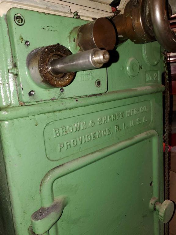

 .
. . So feel free to blame it on me. I can still run pretty fast when I need to.
Not MC, but fun for the gearheads, Surface Grinder build.
in Watering Hole
Posted
HA! I got more questions than you can shake a stick at.
I know nuttin about this stuff.
I have no problems with the mechanics of how it works and building what I need, It is the control parts that have me spinning.
This first part is just to make the table cycle back and forth, then I get to figure out how to make the table feed a set amount at the end of each stroke.
I may have to do some serious brain picking on you.