

winston66
-
Posts
97 -
Joined
-
Last visited
Content Type
Profiles
Forums
Gallery
Events
Store
Posts posted by winston66
-
-
OOPS
I missed that.
Cheers , winston66

-
That was a quick response,
As you probably have the bike partially dismantled I would seriously consider checking the valve tappet clearances. That should not be a big job at this stage. Too little clearance can contribute to hard starting and some other problems. (ie. the exhaust popping)
Adding a teaspoon of oil to a cylinder and then doing a compression test will indicate that if the compression pressure increases, that there is some blow by of the rings.
You indicated that you did this and the pressure increased.
If there is no increase , from the initial measurement, in pressure and the cylinder remains considerably lower than the other three it indicates a possible valve problem.
However I would still check the tappets for the proper clearances.
A vacuum leak on the cylinder side of a carb. can also contribute to popping on the respective exhaust particularly on deceleration.
If you are considering a replacement ecu iginiter unit I would seriously suggest that you invest in one of the Dyna dk3 units that is made especially for these bikes.(plug and play)
believe me, I invested in one even though the original unit was working , the difference that it made to my Royal Star was amazing.
Do a search on the forum for some more information and specifications on that product.
For me it was well worth the $300.00 it woke my bike up.
Cheers , Winston66, Northampton, Western Australia
-
I do not know about all of the preceding stuff as I did not bother to read it all.
I noticed that the Volt Ohm meter in the first pic was set to the lowest scale that means to me that the resistance of the field coil to the earthed case was 3.4 ohms , which according to a subsequent post was the factory specification , so I do not really know what every one is talking about , if that reading is what it should be
Cheers , winston66, Northampton , Western Australia:fingers-crossed-emo:backinmyday:
-
A couple of things.
On my 96 XVZ the radiator overflow is a coolant recovery system and the radiator overflow goes into a recovery bottle adjacent to the battery. (no dribbles from the resivour outlet)
The fuel pump will only run for a short time at the ignition turn on and then stops until the motor is started and the ecu sees a signal from the crank position sensor that the engine is running.
With the liquid gauge to test the float bowl level , turn the ignition on and off a few times in order to prime the carbs. properly and to establish that the float valves are working properly. This test is not to establish how much fuel the float bowls will hold, but at what level the fuel will obtain when the motor is running.
I believe that with the carb. diaphragms and attached long needle there is supposed to be a small O ring in the throttle body for the needle to sit in in order to properly regulate the fuel delivery. can you research this and check.
I SUSPECT THAT YOU SHOULD CHECK AND ADJUST THE VALVE TAPPET CLEARANCES IF THEY ARE OUT OF SPEC.
After all of this why do you not get the ignition module either checked or replace it with a known good one for a test as to weather it is the major cause of the miss fire problems as stated in the workshop manual.
I hope that this helps,
Cheers , Winston66,
Northampton, Western Australia
-
I do not understand you descriptions. of the resistance readings for the switch.
If when using an ohm meter to check for either the resistance or the continuity of a circuit essentially one side of the devise being tested must not be connected to anything that can provide a parrell path back to the devise. Ie one side must be an open circuit.
If testing a switch set the ohm meter to the highest value scale, connect the ohm meter across the devise to be tested and with the switch in the open position the meter should read an infinity amount of resistance , ie 10 meg ohms or more.
then set the meter to the lowest value resistance range , close the switch and if the switch contacts are good there should only be a very low value ohms reading which is equal to the residual resistance that is caused by the resistance of the test leads.
You can test the test leads by touching them together and seeing what the ohm meter displays, this is their residual resistance.
A zero or very low value displayed ie one ohm or less being displayed when the switch is closed indicates that the switch contacts are in good condition and that the switch is OK.
I hope that this means something to you.
Cheers ,
Winston66 ,
Northampton , Western Australia
-
This is probably a dumb question or otherwise a dumb suggestion.
For my two cents worth , have you tried replacing the fouled , dirty spark plugs with new and properly gaped ones?
Cheers .
Winston66,
Northampton , Western Australia
-
On my 96 XVZ the mirror fastenings had opposite direction threads so you will find that mirror undoes in the opposite direction.
That is why the fastening nut has that groove ,in order to tell you that it is a reverse thread.
Cheers,
Winston66,
Northampton , western Australia
-
Winston66,
Western Australia.
Sounds like a positive 12 volt supply problem to me, a bad positive supply connection on the clock circuit could have the effect of not supplying enough voltage to the clock when cranking the motor over and it is possible that the clock would then drop out momentarily whilst the battery voltage is depleted by the heavy draw for the starter.
This could also be a sign that your battery is loosing some of its capacity and may be starting to fail.
I suggest that you monitor the battery terminal voltage whilst cranking the motor and if it drops below 10 volts whilst under load then make sure that it is charged up properly and be prepared to get a replacement.
Best of luck,
Cheers, winston66
-
For my money,
If I wanted a black exhaust, I would firstly sand blast to get rid of any shiney chrome,then I would let the pipes go rusty and when covered with a thin layer of rust oxide I would apply an all over coating of weak phosphoric acid (about 5%) this will cause the red rust to turn black.
The finished effect wont look very nice but will be patchy black and if you were not happy with that just apply some high temp black engine enamel, which would be easy to touch up at any time in the future.
Total cost would be bugger all.
Cheers, Winston66, Northampton Western Australia
-
Winston66, Western Australia.
I have a similar problem but as parts etc. are hard to get over here ,I am considering taking my bars off and then getting them altered by having the respective bends in them slightly altered (re bent) in order to help my hand position to line up better and be more comfortable for me.
Does any one have thoughts about this.
Cheers Winston 66
Ps. my ride is a 1996 XVZ Royal Star
-
Winston66, From Down Under,
When ever I have experienced a problem with the lights being something like this, Most times the problem has been found to be a compromised earthing point, This will cause spurious electrical paths usually back through various other lights etc. or other electrical items, and then you will get some weird or funny faults showing up.
I can only suggest that you carefully inspect each and every earthing point and connection , clean and re tighten everything and also check, any and all of
the available earth wiring with an ohm meter for continuity , Make sure that is NO resistance to the bike frame as you go ,and also to the battery negative connection.
I am almost prepared to lay odds that this is the cause of your problems, Check the earth wiring for continuity at all connection blocks. Both sides.
Cheers
Winston66
-
The expanding
Teardrop Trailer Build
By Winston Lee
18/04/2013
Concept.
I wanted to go touring, and camping, on my motorcycle.
But did not want the complexity and all of the associated hassles of roughing it, or erecting tents. Or sleeping on the ground, or fighting with a swag, or blow up mattresses etc.
Besides that is a lot of stuff to pack on the back of a motorcycle.
So after some considerable thought I decided to construct a pull along teardrop trailer, for my motorcycle .
I wanted to incorporate some unique design features that could only enhance the pleasures that would ensue with its use.
With my limited skills and capabilities this build had to be simple and economic in design, and concept, and to use easily available and inexpensive parts, and components, and the tools that I had to hand.
I selected a readily available small trailer chassis kitset that I could easily assemble, and when completed it would comply with the Western Australian motor vehicle registration specifications. (it had the factory supplied required Vin. number etc.) And came complete with the full suspension , Spare wheel, Trailer hitch, safety chain, lighting ,and wiring loom, and suitable 7 pin plug. Etc.
The assembled dimensions of the chassis were most suitable for the intended purpose and did not need to be altered in any way.
At this time I was not overly concerned with the finished gross weight of the trailer as the kitset components weighed in at about 65 kilograms and I was allowing for a possible all up finished laden weight of around 190 to 200 kg. My towing motorcycle in my opinion is just one of the best, being a Honda ST.1300. It has plenty of power and certainly can go fast enough for me. We are limited here anyway in Western Australia to a maximum of 100 kilometres per hour whilst towing, and a maximum of 110 at other times when on the open road .
=======================
Body Design,
I wanted to be as economical as possible with the materials needed, so I elected to construct the body from aluminium checker plate (diamond pattern), and it was to have a plywood floor.
The body would initially be a one piece shell and when finished would then be cut in half across ways and the rear portion would be attached to both the chassis and the rear portion of the floor, the floor would be in two pieces also, (details of this later).
The front portion of the floor would be on top of and overlap the rear portion.
The rear portion of the body would be perminately attached to the rear main part of the floor and the chassis. The extending front portion of the floor, and body, would then be able to slide forwards away from the rear part of the floor and body, and up the draw bar, towards the towing hitch. Supported by Teflon sliders and some small fabricated rollers.
The effect of this would be to extend the opened ,overall length of the teardrop body from the designed 1550 mm (closed length) , for towing. To a total extended length of 2400mm, This would enable a full length for a (bed) of some 1020 mm. wide, (the chassis width.) by 2000mm in length . Ie. some(50) mm. longer than a normal bed (which is 1950mm) ,and then there would then be an area of some 400 mm. deep, accessible through a rear hatch as a totally separate storage area (some might call it a kitchen.)
Access to the bed area is through the sides at the point where the body divides and can be an opening of between 800mm. to 900mm. in width, depending on your preference.
I subsequently have constructed a couple of separate cover panels which clip on to the side and the top, over the opening, these will provide adequate weather cover for the opening in the top and one side. These panels unclip when packing up and are stored on the floor of the front half, and when packing up I place them under the folded mattress, before sliding the two halves of the body together.
There is also a very light weight awning system which attaches over the opening and will give full shade and rain protection if needed.
I wanted to minimise the cost of the single most expensive components, ( The aluminium cladding for the body), Consequently the sides were shaped and designed to be both cut from a single 2400 by 1200 mm sheet of 2.4mm aluminium, don’t forget to reverse the profile for one side so that the outside surfaces will have matching patterns to the outside.
The top was cut from a single piece of 2400 by 1200mm 1.6mm aluminium . The top was cut
to be finished 20 mm. wider in total than the finished width of the outside of the body. The hatch for access to the rear storage area necessitated the subsequent purchase of a suitable sized extra piece of cladding. This was sourced at the time of constructing the two clip on cover panels.
=======================
Chassis Considerations and adjustments
For stability when towing. The draw bar length needed to be adjusted to a ratio that is dictated by the wheel base width, (or track). This needs to be minimum of one point eight times the wheel base width. I feel that a ratio of two times is even better.
To achieve this the draw bar was extended by approx. 650mm. from the front of the chassis, this gave an approx. total length of 2300mm from the axel position.
At this time I also extended the total length of the draw bar to project 300mm past the rear of the chassis this gave me a firm attachment point for the rear of the body and also a suitable mounting position for a bumper, or in my case a place to mount the spare wheel.
As the wheel track is 1200mm. from centre to centre of the tyres, and the draw bar length 2300mm from the axel to the tow hitch, this equates to a ratio of 1.9, and I found that with these dimensions the trailer was well behaved and tracked the motorcycle perfectly and there was no induced swaying whilst underway.
Trailer Hitch
This one is quite important.
The supplied hitch is of the standard design and suitable for up o 750 Kg.
However for use with a motorcycle, I would recommend obtaining an aftermarket unit that swivels around the axis of the drawbar. This is for safety reasons, because if your bike ever falls either off the side stand, or is dropped, even at a low speed, if the hitch does not swivel, some quite serious damage will be caused to the attached hardware on the motorcycle.
Draw bar weight,
I feel that this is very important and some care must be exercised when loading the trailer, I have found that for me, a tow hitch weight of around 15 kilograms when laden, is acceptable, but you will have to experiment a little in order to find out what will suit your particular situation.
With the Easy Tailer chassis I took the trouble of dismantling the leaf springs in order to remove the second leaf from each spring. In my opinion the overall laden weight of the trailer did not need the extra helper spring leaf, and doing this actually improved the handling of the laden trailer. Whilst doing this I also slipped a piece of suitable plastic irrigation hose over the bolt that retained the rear of the spring in the slipper, this reduced the transmitted noise when the spring moves.
After assembling the chassis and attaching the springs, when fitting the axel I turned it upside down and placed it on top of the springs, this lowered the chassis approx. 40 to 50mm which will reduce the overall finished height of the trailer. It also lowers the centre of gravity.
After fitting the stub axles and the finished draw bar, the chassis was checked for squareness by measuring from the back corners to a centre point on the attached tow hitch, when these measurements were the same I also checked the distances from the ends of the stub axles to the same point on the tow hitch in order to make sure that the trailer would track properly.
When all was square the chassis assembly bolts were checked for tightness and then any joints that were suitable on the chassis were welded .
Tyres
The tyres and wheels that were supplied were 12 inch rims fitted with 4 ply high speed tyres rated for 120 kph. And 480 kg. I found that an inflation pressure of 25lbs was suitable for me.
Lights
Standard trailer lights, ie, side, running, stop, and turn indicators, with incandescent bulbs were supplied with the chassis components.
I felt that these were quite satisfactory for my needs, but if something up market was required you could obtain some suitable, led type, there is a very wide choice on E Bay.
Sliding Floor
This was achieved by making several sets of rollers and then inserting them in the main floor as shown, see the photos for illustrated details.
The rollers were constructed from a piece of 1 Cm. Thick nylon cutting board. I used a 30mm. hole saw to cut out the wheels, and the axles are from some ground down 5/16 inch bolt shafts, these were then held in place with some appropriate stainless steel strapping, and countersunk ¼ inch bolts.
With hindsight the roller idea is probably a bit too much , I now think a suitable result could be obtained by using thin strips of Teflon fastened on the main floor, (glued), and the sliding surface faced with something like melamine.
Internal divider
This will be needed in order to divide up the internal space as you require as well as providing a very strong bracing for the sides and also supporting the top.
This was constructed from a suitable piece of sign white. Bent to shape to give recessed area for clearance for your feet, and to make a shelf in the rear storage space, This divider adds a tremendous amount of needed reinforcement and stiffening, to the sides and the top.
=======================
Trailer build
Step 2
Sourcing parts and hardware.
1 The basic trailer chassis,
Carlex Pty. Ltd. (Easy Trailer Service Centre) Email sales@carlex.com.au
830TA Trailer Trailer Model LCI-830TA
Spare Wheel, 4 Stud
Trailer Stand
Tel 1300 881 787
These people have a comprehensive range of product , contact them for their product catalogue etc.
See appendix 1 for the specifications
2 The aluminium sheeting for the cladding, and the right angle al. extrusions etc. contact any of your local sheet metal suppliers for their selection of product and prices, I used aluminium diamond pattern checker plate for both the sides (2.4mm.), and the top (1.6mm.) Full sheets 1200mm. by 2400mm.
2 General hardware items. Locking Latches, and general
3 assorted bolts and other fastners etc, The local Motor vehicle and hardware parts supplier.
4 Screws, and Sealed aluminium pop rivets, Bolts etc. The local Bunnings.
5 Wooden components, plywood etc. Bunnings.
6 Silastic adhesive Bunnings.
==========================
STEP 3
SPECIAL CONSIDERATIONS
West Australian Government legislation.
See attached extract for current requirements.( if I can find it)
For your build you will have to consider some if not all of the following points.
1 Weight
2 Width
3 Height
4 Lighting
5 Towing speed (Tire ratings and sizes)
6 Draw bar length
7 Tow hitch weight
8 Overall weight
9 Tyres , Specifications, Sizing, Speed and loading,
10 VIN. Number
11 Vehicle licensing
12 Driver (licensing) requirements.
13 Fuel consumption. Towing vehicle
===============================
STEP 4
Insurance and Legal Considerations.
1 Check with your Insurance providers as to their requirements in regard to your special situation and requirements, and to ascertain what disclosures they will require from you.
2 Will you and your Motorcycle comply with their requirements? or will you have to canvas the providers to find one that will be interested in your business.
3 If you choose to use any of the information provided in this blog, it is solely at your own risk and the author is absolved from any consequences or happening that might ensue by your actions.
==================================
Appendix 1
Ph.1300881787
Basic trailer chassis, information.
Trailer specifications
Model 830TA Chassis Trailer-Rigid
Bed size 1220x1016mm tare weight 65 Kg.
Compliance ADR/ECE .
Springs HT. Slipper (660) Kg.
Wheels 12” white Spoke Steel (5mm)Tyres 60 Psi, 4 Ply, High Speed
Hubs/ Axle 4 Stud, Cast Iron(990) Kg. Bearings, 2” Fully Tapered (990) Kg.
Bed Height 475 mm. Coupler 50 mm. 750 Kg.
Coupler Height 410 mm. (Hitch) Frame “C Section 1.5x2
Hitch Standard Regulation 750 Kilogram
Safety chain Regulation stamped 1000 Kg.
Drawbar 700mm,-2.5”x2” Lights ADR Combination Type
Wiring 7 Pin Flat Loom
Lights Combination/stop/running/turn signal indicator. With Optional / Amber side lamps
=========================================
Appendix 2
Concept drawings
The following few drawings are an attempt to show some of the design concepts and ideas that I used to ratify my final design, in some instances the final design changes quite a lot from these original sketched ideas and this was because of having some new ideas and also having to adapt certain features to suit the available materials etc.
You will get the idea.
These were my initial sketches which I used to prove the concept.
The final build changes somewhat from these examples. As some minor modifications were incorporated as the build progressed, and I had the opportunity to improve, some aspects of the design. As I thought of them.
I actually built things to fit as I went along and ideas came to me
All the measurements and notations shown, are nominal values only. But I made some effort to try to make the drawing to scale.
The dotted vertical lines that show the centre portion of the floor lifting vertically, this was not used in the final build, as I decided to make the floor in two pieces, then to divide, and then slide over itself.
The final size of the body was dictated by the stock size of the kitset trailer chassis, and the overall size of the top of the body was dictated by cutting it out from only one sheet of aluminium.
The drawer bar was lengthened to 1800mm from the axle and then 300mm rearwards to provide extra support for the body and the spare wheel.
The zig zag dotted line towards the rear shows the internal divider which separates the rear storage compartment and also adds a tremendous amount of bracing, support for the roof and stiffness to the body.
The square item on the draw bar could be provision for a esky or other storage area, but that item would have to be removed when opening out the trailer body. I felt that this was not practical, and my esky is carried inside whilst travelling.
Well that is all I have to say folks.
I hope that you found my little exercise interesting and possibly informative.
My next exercise is the construction of a single wheel (uni go) type of pull along trailer.
This utilises as the main components the front wheel, complete with the telescopic forks, and the chassis of a discarded scooter. Then there will be the body build and the construction of the special draw bar and hitch coupling.
Cheers.
Winston Lee Western Australia.
Email meontop@hotmail.co.uk
-
Winston66, northampton , Western Australia.
Try a search , Royal Star , technical, 32mm carb swap by lyn nichols
Cheers
Winston66
-
Winston66.
I am not sure but that looks reminiscent of an adaption bolt on called ghost wheels.
Cheers , winston66
-
Winston 66.
From down under in Australia.
I was just wondering if there was anyone out there that could help me with a replacement ,Low fuel level sender that would suit my 1996 XVZ 13ATH Royal star.
I believe that the OEM part No is 4NK-85752-01-00 A working used one would be acceptable.
I did come across A used one on Pinwall cycles e bay site but the price was too high and when added to the shipping of US.$36.00, It was too much for me, A new one seems to be priced any where from $80.00 to $120.00 plus shipping
I have here a set of 4 carb. slider diaghprams . Keyster SD1 Marked Suzuki SSX7500/1100,
Yamaha XS1100 .I purchased these new from Sirius Concolidated last year but have found that they will not fit my smaller 28 mm carbs . They said that they were the correct ones .
They measure overall diameter of 72 mm with a hole for the slider of 29 mm. Rough measurements.
the fitment on my 28 mm carbs cover plate is about 63 to 65 mm. So these ones are no good to me They are still in their original unopened plastic packing and have been kept in the refrigerator since I received them.
Perhaps a swap or something could be arranged.
I would be happy to pay some reasonable amount for shipping etc.
If anyone is interested my email is meontop@hotmail.co.uk
Cheers to all,
Winston 66
-
Winston 66, Western Australia.
well hello again everyone.
it has been great to see your comments and get the feedback, it certainly helps me to clarify my thoughts about this idea of mine.
Today I have ordered a stand alone automotive rev .counter as well as checking out the Venture Virtual Tach. Redlined and now I can see How running in fourth could help with getting into a better load range for the motor.
It will be most interesting to see how this exercise works out.
My rudimentary reckoning tells me that give or take a little bit that with the V Max gearing that at 4000 rpm my road speeds in the various gears would be something like this.
I have not taken into consideration any differences between the standard Royal Star gearing, And or what the Mk11 Venture has , I believe that there are some small and subtle differences between different models.
1 st 30 mph. 48 klm @ 4000 rpm.
2 nd 44 mph 71 klm.
3 rd. 63 mph 100 klm.
4 th. 77 mph. 123 klm.
5 th. 96 mph. 155 klm
It seem to me when looking at those figures that the poor old motor will still be struggling along even at 4 th. gear at 60 mph. or otherwise 100 klm. Per hour, when it will be doing something like about 3500 rpm.
I had noticed that before ,when the RS as still a two wheeler that it did not feel properly comfortable until the road speed was above 65 or 70 Mph. Then everything just seemed to smooth out.
Now after all that, I am even more interested in doing the 32 mm. carburetor swap that was mentioned by Skydoc 17 in a previous post.
I will just have to try and source the necessary parts which will be one heck of a job over here.
Well that's all for now folks, so until.
the next chapter, Cheers to all,
winston66
-
Winston 66,
I have read that a four into four is possibly the worst type of exhaust system to have as it is a power robber etc.
Now this is what I have on my 96 Royal Star and when towing the gas used seems to be very high , on my last trip I averaged only about 25 to 28 Mpg US this was computed by dead reckoning,
It is a little difficult to be precise as I have to adjust all the figures from liters , kilometers ,to miles, and USA. gallons.
But for the metric minded how about an estimated 9.5 Klm. per liter, or otherwise about 10.5 liters per 100 Kilometers.That should be close enough for this example.
Now my question is this, what if anything can I do with he present 4 into 4 exhaust system that i have and does anyone have some insight as to any possible improvements could be expected by changing some stuff.
Lets hear your views and opinions.
Cheers , Winston 66, Western Australia
-
Winston 66 Western Australia.
I dont know if this will interest anyone out there, but My thoughts were much the same especially about the safety factor with my Royal Star'
My solution to an upgrade was to search E bay and I found a suitably shaped and the correct fitment replacement mirror, The big difference was the ones that I wanted had LED turn indicator lights integrated into them which I felt would add tremendously to the visibility of the ride for any on coming traffic from an oblique angle from the front. if and when I was turning and using the indicators.
I could not get OEM. lookalike ones so the chosen ones have a black carbon fiber appearance but IMO they look ok and with the added flashing signal lights i am happy and I do feel there is an improved safety factor.
Wiring them into the existing harness was easy and only took a short while.
Cheers Winston 66, Western Australia
-
my miles per gallon go down noticeably when there's a headwind. Riding at 60mph with your rig, I'd keep it in 4th gear most of the time, even with the vmax rear gears.
Your rig is the trike, right? so is it an outrigger style trike that keeps the Yamaha rear end?[Winston 66,
Yes Randy
/QUOTE] Thanks for the tip I will be trying that, and yes the trike is an outrigger style that just bolts on , we designed and I made it here I did not have to alter the RS in any way ,it used existing bolt hole attachment points and I did not even have to weld any brackets etc to the bike frame.
The outrigger design utilizes independent,trailing arm suspension with air over dampening,and incorporates an anti sway bar for stability whilst cornering.
The wheels are 15 inch X 7 Volvo /early GM stud pattern and uses 205X15 Perilli tires
with about 6 to 8 mm toe in each side.
The anti sway bar is tuned with different length linkages to keep everything level in order to compensate for the road camber and in straight line travel so that you dont have to fight it whilst travelling in a straight line on a cambered road.
The system works, and is easy to control, has great stability , is great when cornering does not need much musselling to get around but most importantly ,as it is regarded as an accessory, there was no need for a vehicle inspection or licencing change.
Cheers to all.
Winston66
-
Winston 66,
Thanks for your comments Earl, This is the sort of feed back that I am after,
In the past I have studied Lynn Nichols write up of the 32 mm. cab. swap etc. I have even printed it out and I was seriously impressed with it and did consider doing it.
Unfortunately here in Australia getting a suitable set of carbs. would be impossible these machines are rare beasts here I dont think that I have seen any other Royal Stars let alone any late model Venturers.
Also because I am so isolated here in the country good technical and or mechanical help or back up for something like that is non exhistant.
I guess that could also be said for the proposed EFI conversion, except that every car these days has an efi set up and parts would be a lot easier and economical to source. There are plenty of small cars to choose from, and a CPU from a Holden(GM) V8 would be suitable as we can reprogramme it.
All that being said , if I could easily source the suitable set of carbs. that have been rebuilt and properly set up for the job, as well the other needed and necessary carburetor parts at a reasonable price I could go that way. I dont think that I would be interested in the cam and valve spring mods . I am not an aggressive rider and I dont think that the extra rev. range or higher cruising speed ability would be of use to me.
Thanks again for your comments.
Incidentally also thanks for sourcing the new clutch slave cylinder ,and the master rebuild kit .the are in and working great.
You will also remember supplying the replacement front discs and the R1 calipers etc.
Cheers Winston 66, Western Australia
-
Winston 66,
Hello everyone, Thank for the comments,
Firstly about the trailer,I got the idea from seeing picture of The Idaho Bedroll camper on u tube and this was my modified concept.
The idea is that it is towed only when the the two halves are pulled in together, the body then only measures 1150 mm. long, and the camping gear (esky,matress,sleeping bag , tools,spares,clothes etc, are packed inside,
Then when stopped the two halves are separated, (pulled apart) by extending the front ,(it slides forward up the draw bar, The body then measures 2400mm, long. and then there is no need to have to erect a tent because there is a full size bed with a good comfortable foam mattress the opened floor area measures 2050 by 1020 and then at the rear there is a separate storage area (galley) for the other small odd stuff.
The total weight with all supplies loaded up is just a shade under 200 Kg.which is quite easy to handle and this includes a full esky with ice and beer.
When towing with either of my two bikes it tracks beautifully and the extra weight on the towing bike is hardly noticeable .
One of my previous trips I covered 450 kilometers in six and a half hours including two 15 minute breaks .I was using the Honda ST 1300 as the ride that day
I arrived home feeling quite fresh and unstressed,
Incidentally the fuel used that day averaged out at 15 kilometers per liter. which is about an increase of another five kilometers per liter over what the Royal star uses ,
So perhaps this might explain somewhat the reasons why I am thinking about the EFI. mod for the Royal Star.
Please keep the comments coming.
Cheers to all,Winston 66, Western Australia
-
Winston66,
from down under in sunny Western Australia.
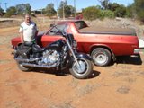
I have just gone around the block on my modified XVZ 1996 Royal Star (I recently converted it to a four wheeler ) whilst towing my newly constructed teardrop camper trailer the distance was about 144 miles.
When I checked the fuel consumption I was concerned that I had used approx 6 Us gal.
this gave me about 24 Mpg. Now I feel that that is not good, especially as our fuel price here is around USD, $6.00 a Us.gal.
So now I am contemplating a fairly ambitious modification IE. changing the Mikuni carb. set up to an EFI. set up. Hopefully in order to drastically reduce the fuel consumption which at the moment I feel is quite excessive
Now I know that this is a pretty radical thing to do.
But at the present time the RS. is running real well ,it starts on the first compression, idles and runs great, no flat spots or backfires and pulls like a train,With an awesome exhaust note from the four separate exhausts. I pulled the plugs today and they looked perfect.,no burning or oiling or discoloration and they were identical in colour etc so I am stumped as to why the hefty fuel usage .
My other mods so far have been to change the diff. to the V Max ratios ,Installed the Dyna 300 Ignition mod.presently on curve 4, I have today dropped it back to curve 3 .There is no dragging, from the brakes, and my speed was limited to a maximum of 60 Mph,(100) Kph. because of our road laws whilst towing.
I must admit that for part of the time There was a bit.of a head wind maybe 15 to 20 Mph.
Now my question is ,has anyone experimented with an EFI set up for these bikes, and or do you have any relevant knowledge that I might find relevant or useful,
I really don't want to attempt to reinvent the wheel ,so to speak.So is there some one out there that can pass on some gems of wisdom.
I do hope that some of you great bunch of guys can have some input and offer me some guidance in this idea of mine.
I will attempt to add some pictures to this post so that you all will can possibly get a better idea of where I am coming from, as well as what I am trying to do.
Cheers to all.
Winston 66 Western Australia
-
Hi Spear,
If you are in Oz .you will be able to get the small slime 12volt pump most likely from the Auto One outlet I have ssn several different models there, one even had a rudimentary pressure gauge as part of the casing , the whole thing was very small ,I have the model shown purchased from the local stock agent here in Northampton in West Aus.
Bot if you want a really good repair kit I recently purchased from the USA the Stop and Go Pocket tire plugger kit.
But you will have to do an internet search , Stop & Go International inc. Crystal Lake Il.
I have not had to use it yet but it is the best repair outfit that I have seen and is very compact, and it has a superior way of plugging the tyre with an easy to use adapter and mushroom headed plugs.
Of course you will also need to have the slime compressor or something similar in order to inflate the tyre.
Cheers,
Winston 66 Western Australia
-
Winston 66,
says, I dont know if your model has the same parameters as my 1996 Royal star , but my Clymer Manual on page 65 states that 9 blinks from the diagonstic trouble code for .
the XVZ TF Models.
Says Emergency stop switch error.Perform perform the procedure described in EmergencyStop Switch Test (chapter 9)
Hope hat this helps .
Cheers ,Winston 66, Northampton , Western Australia


Firing on two of four!
in Royal Star and Royal Star Tour Deluxe Tech Talk
Posted
Here is a reference to the Dynatek ignition that I mentioned,
Dyna 3000 Kit D3K7-4 to suit Yamaha Royal Star 1996-2000
If you look it up you will find some interesting reading.
Cheers, Winston66