

Freebird
-
Posts
17,720 -
Joined
-
Last visited
-
Days Won
206
Content Type
Profiles
Forums
Gallery
Events
Store
Posts posted by Freebird
-
-
Repairing Broken Windshield Trim Tabs
The great things about this forum is the fantastic ideas that we get from each other. This one is so good and so easy that I sure would like to take credit for it but the fact is, the idea came from expanding on a post made by SteveO where he used these type clips to take the slack out of the holes that the tabs actually snap into. His post gave me an idea for repairing the tabs that were actually already broken.
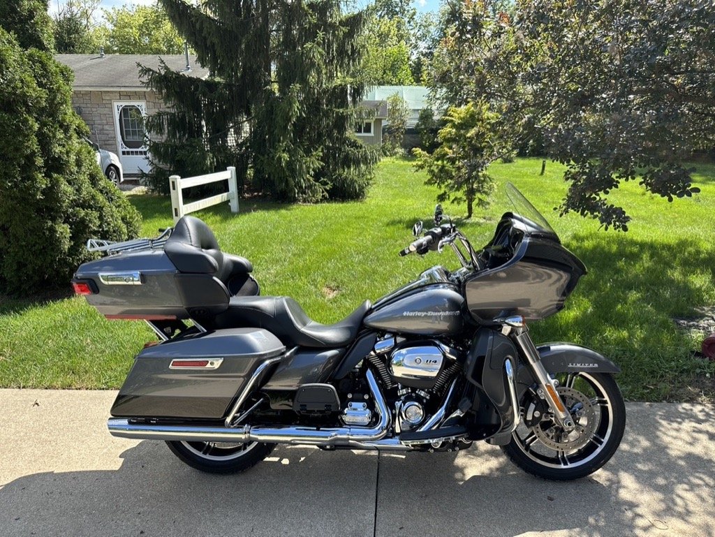
The tabs on the back of the plastic chrome windshield trip break very easily. Most people who have ever had the piece off, have broken at least one of them. The following is an easy way to repair them to better than new condition. I had a couple of them broken off and this is so much better and stronger, I actually broke the other two off and did this on all of them. Here is a picture of one of the broken tabs.

At most auto parts stores, you will find these clips. They were called "Speed Nuts" at Autozone and I believe these were size 14. It was the smallest ones that they had. Here is what they look like when you take them out of the package.
Now...as the top picture shows, there is a center "bar" or "Support" in the center of what is left of the broken tab. In order to slide the "speed nut" over the broken support, you will need to cut the center out of the back of the clip. Also, because the clip is just slightly too wide, you'll have to shave just a bit off each side of the back side of the clip that you just cut the center out of. I used a Dremel tool with a thin cutting disk to do both. Here is what you end up with.
Now, simply slide the clip over the broken support and you have a brand new clip that fits right into the slot where it should. It fits pretty tight but just to be sure, I filled the grooves with two part epoxy. They aren't going anywhere.
-
 1
1
-
-
Thanks to Cougar for this excellent write-up FYI- Picture's of Rear Tire Removal
Well, With all the searches and Folks Changing out there REAR
TIRE. I learned A Lot today from you guys! And I said to myself
** SELF ? ** why not try this and takes some pics for other folks?
Ok, here go's...
I did what most of you said !
I did remove the Bags Because I had a hard time getting
that little part out for my new Bag Rails. So they were off
and Thats when the light went off and figured I have these
Brand new Michelin Commanders laying around so I went
to work on this project today.. With a Few emails to Mr.
FreeBird! I got the Job Done! (thanks)
Then I went Ahead and removed Both Mufflers (tell ya why in a bit)
http://www.venturerider.org/wheel/thumbnails/attachment_029.jpghttp://www.venturerider.org/wheel/thumbnails/attachment_007.jpghttp://www.venturerider.org/wheel/thumbnails/attachment_025.jpg
Then I Used a 1 1/16" Socket and took the main bolt off
http://www.venturerider.org/wheel/thumbnails/attachment_019.jpg
Then Remove the Rear Brake Caliber and place it on the
passenger foot rest. This is also a good time to loosen the pinch bolt on the right side. The axle will NOT slide out if you don't.
http://www.venturerider.org/wheel/thumbnails/attachment_014.jpg
Then undo the bolt for that swing arm thingy.
http://www.venturerider.org/wheel/thumbnails/attachment_011.jpg
Now this is were I was glad I did remove the Left side bag and
Muffler Cuz I could not for the life of me get that darn MAIN AXLE
BOLT out with out having to take my socket extension and hammer
it out..
http://www.venturerider.org/wheel/thumbnails/attachment_003.jpghttp://www.venturerider.org/wheel/thumbnails/attachment_010.jpg
Here she comes!
http://www.venturerider.org/wheel/thumbnails/attachment_005.jpg
KEEP IN MIND THAT YOU PUT THIS WASHER BACK IN THE RIGHT
ORDER WHEN PUTTING BACK TOGETHER!
http://www.venturerider.org/wheel/thumbnails/attachment_008.jpg
After the Shaft gets about half way is when I could pull the rest
of they way on my own.
http://www.venturerider.org/wheel/thumbnails/attachment_005.jpg http://www.venturerider.org/wheel/thumbnails/attachment_027.jpg
Note: My bike was on a Lorin Lift.
So What I did was have that rear tire about a half inch off the ground
when I pulled that Axle. (worked great)
http://www.venturerider.org/wheel/thumbnails/attachment_018.jpg
Then I lifted just a bit more and pulled from the right side until
the tire kinda fell on its own.
http://www.venturerider.org/wheel/thumbnails/attachment_016.jpg
Now the FUN PART!
I just kept lifting
http://www.venturerider.org/wheel/thumbnails/attachment_024.jpg
MORE
http://www.venturerider.org/wheel/thumbnails/attachment_026.jpg
AND MORE
http://www.venturerider.org/wheel/thumbnails/attachment_015.jpg
AND MORE
http://www.venturerider.org/wheel/thumbnails/attachment_017.jpg
Man it was getting Scary! sheesh!
http://www.venturerider.org/wheel/thumbnails/attachment_021.jpg
Even with more room left the lift on my jack the tire
Came right out! *VBS*
PLOP!
http://www.venturerider.org/wheel/thumbnails/attachment_004.jpg http://www.venturerider.org/wheel/thumbnails/attachment.jpg
Put back together in reverse order ~S~
I also did this as well. Took the main rear Diff off
and there was no grease on the Splines.
http://www.venturerider.org/wheel/thumbnails/attachment_013.jpghttp://www.venturerider.org/wheel/thumbnails/attachment_020.jpg
http://www.venturerider.org/wheel/thumbnails/attachment_002.jpghttp://www.venturerider.org/wheel/thumbnails/attachment_022.jpg
http://www.venturerider.org/wheel/thumbnails/attachment_009.jpghttp://www.venturerider.org/wheel/thumbnails/attachment_012.jpg
http://www.venturerider.org/wheel/thumbnails/attachment_028.jpghttp://www.venturerider.org/wheel/thumbnails/attachment_006.jpg
This is what my Rear Brake Pads look like
at 5,100 miles.
http://www.venturerider.org/wheel/thumbnails/attachment_023.jpg
then I did the Front! (easy)
And the lift kept the bike very stable even after the front
Tire was removed.. I am impressed with the lift.
When my tires get done being Mounted and Balanced I will go into
the HUB and get that all greased up as well!
(this was very simple after I got it all figured out and the help
from reading what you Pro's had to say. Its just sometimes I need
to SEE a picture to make me understand more *LOL*
I hope this will help folks if needed.. I know I sure could have
used something like this.
( this is on a 2K MM with 5,100 miles on her)
Jeff
P.S. PLEASE add any comments in case I made a mistake !
Thanks!
NOTE: this Job could be done in 30 Min's with Pictures *LOL*file:///C:/VentureRider/wheel/showthread.php_files/rasberry.gif
PLEASE READ !
OTHER NOTE'S BY,
Denden,
When you're re-assembling it...
After you put the driveshaft in, put the differential on but leave the 4 nuts only finger tight.
Then install the wheel and axle. Torque the axle nut to 110 ft/lbs. After the axel is torqued, THEN tighten up the 4 nuts on the differential.
John Drummond,
"Wrenchman"
When you go to install the drive shaft a small diameter wire like an old antenna mast works great for holding the yoke up so you can slid the driveshaft in. Once the shaft makes contact with the yoke you can pull the wire out, and slid the shaft in to the yoke. This might take a try or two to get it in but works pretty well for lining up the yoke.
Buz Rutan,
"Naturbar"
The author of the article says "I could not for the life of me get that darn MAIN AXLE BOLT out with out having to take my socket extension and hammer it out.." here is my addendum: On my 07 RSMTD - at the end of the axle shaft there is an place to use an Allen Head wrench - if you will turn it counterclockwise (loosen it) the axle shaft comes right out with no hammering (clockwise - or tightening to replace shaft)- also if you have slight pressure on the wheel assembly (i.e. tire resting on floor)while removing the axle it makes it much easier to remove.
-
Second Generation Torque Specifications
-
FAULTY IGNITION SWITCH
Temporary Repair
A few weeks back I stopped for gas, and when I turned the key on there was no electrical power, except for the radio. There was no lights on the dash, no headlights, or any other power, except for the radio. After checking all the fuses, which were okay, it was suggested the ignition switch could be the problem.
To get to the ignition switch wires you will have to remove the seat and the top cover by the key (two Allen head bolts), and then remove the Fuel tank, by first removing the breather tube on the top of the tank, the electrical connection and the fuel line (under the tank). There are two Allen head bolts at the front on each side of the tank, and one bolt near the seat, before you can remove the Fuel tank. After removing the fuel tank there are two plastic covers on each side of the switch, which are held on by a small Phillips head screw and a plastic plug.
http://www.venturerider.org/switch/image001.jpgReferring to the manual, Section 8 page 2 stated that switches could be tested for continuity. The manual states, on the main switch there should be continuity between the brown/blue wire and the red, and between the blue/yellow and blue/black wires, when the switch is turned on. I used a multi meter and started checking the wires for continuity. This should be done on the backside of the plug, to prevent damage to the plug connections. I found that I had continuity between the Blue/Yellow Wire and the Blue/Black Wires, however I did not have continuity on the Brown/Blue Wire and the Red wires. I used a 10-gauge wire and inserted it on the backside of the plug between the Brown/Blue Wire and the Red wires and then I had power on the dash and fuel pump started clicking. Therefore, I spliced the Red wire and the Brown/blue wires and connected a 10-gauge wire to the spliced ignition switch wires. I ran this new 10-gauge wire to the handlebars and connected these to a 50-amp single pole toggle switch, which I taped to the handlebars. Please note the 50-amp switch is most likely much larger than required.
http://www.venturerider.org/switch/image003.jpghttp://www.venturerider.org/switch/image005.jpg
New Switch
http://www.venturerider.org/switch/image007.jpg
Wires (on new switch)
http://www.venturerider.org/switch/image009.jpg
When there is no continuity between the Brown/Blue wire and the red wire there will be no power, except for the radio. These wires close the circuit to the main fuse, battery, starter relay, starter motor, and the Start Switches (including the clutch, neutral, side stand, and stop switches).
-
Adjusting Steering Head Bearings
Today we are going to look at a very simple method of adjusting your steering head bearings. Loose steering head bearings are a fairly common problem on both the first and second generation Venture and probably the Royal Star also. At some point, you will most likely want to do a true service on these bearings. That is a much more complicated and time consuming job which requires completely removing the handlebars, top tree, and on at least the second generation Venture, the front faring..inner and outer. I've done that job and it takes several hours. It should be done at some point though because you will probably, at some point, want to repack the bearings and that requires the more complicated method.
If your front end seems loose though and you simply want to tighten it up a bit, it's a very simple job that can be done in about 30 minutes. You will need a lift to do this job as the front must be completely off the ground. As you can see from the following picture, it does not need to be high in the air...just make sure the front tire is not touching the ground. Once you have the bike lifted, gently push the handlebar one way or the other and see how loose the front is. In my case, the front would fall to one side or the other without me even touching it unless I had it perfectly centered. That is too loose. The front should stay where you have it and if you gently push it one way or the other...it should gently come to a stop but not be binding or hard to push. If you gently push the bars so that it bounces off the stops, it should rebound gently and stop...maybe even ever so slightly oscillate back just a tiny bit but if it oscillates back and forth 2 or 3 times, it is definitely too loose.
http://www.venturerider.org/steering/lifted.jpgThe next thing you will need to do is slightly loosen the top nut just below your handlebars. An open end wrench works great for this but if you don't have the right size, you can protect the finish with a rag and use a pair of Channel Locks.
http://www.venturerider.org/steering/topnut.jpgIf you look just underneath the top fork brace, you will see two locking nuts. These nuts are slotted and locked together with a locking washer with a tab. You do not need to pry out the tab as we are going to simply tap and tighten both nuts together.
http://www.venturerider.org/steering/lockingnuts.jpgBelieve it or not, we are almost done. Simply take a long screwdriver and place the blade in the slots in the nuts. Tap lightly with a hammer to tighten the nuts. Be careful here. You will be amazed at how little you have to tighten these nuts to make a big difference.
http://www.venturerider.org/steering/screwdriver.jpgAfter tapping, gently swing the front end. If you gently swing the front end to where it gently hits the stops, it should rebound slightly and come to a gently stop. It should not bind or be stiff but should not oscillate back and forth. If it bounces off the stop, and then rebound and hits the stop again...it is too loose. If it rebounds and gently stops....you are about right.
Once you get it right....simply retighten the top nut and you are done. Very simple job that takes about 30 minutes.
-
 1
1
-
-
http://www.venturerider.org/spoiler/image002.jpg
INSTALLATION INSTRUCTIONS
Trunk Lid Spoiler w/ Light
STR-4XY62-03-XX
Royal Star Venture (XVZ1300TF)
http://www.venturerider.org/spoiler/image004.jpg
Please read and understand these instructions completely before installation to avoid injury to your self or damage to the motorcycle or accessory,
Dealer: These instructions contain important information for future reference and must be given to the customer.
1.Parts List:
Item
Part Name
Part Number
Description
Qty
1
Spoiler W/ Light
Molded ABS
1
2
Wire Guide
24” rubber “D” extrusion
1
3
Screws
Phillips head self tapping screws
3
4
Flat Washer
Steel
3
5
Rubber Washer
Rubber
3
6
Drill Guide
Plastic Strip
4
7
Drill Template
Paper
1
2. Preparation:
a) Clean trunk lid thoroughly
3. Installation:
a) Place spoiler upside down on workbench use a towel or soft cloth to protect paint.
b) Center hole in drill guide with mounting stand off and attach to spoiler with a small piece of tape (fig. 1). Repeat for the remaining 2 mounting stand offs. Locate 4th drill guide under end of light with hole centered on spoiler (fig. 2). This will be used for wire routing.
c) Mark the centerline of the lid with of masking tape using latch button as center (fig. 3).
d) Center spoiler on trunk lid with back edge just above “Yamaha” logo approximately 2-1/4” from the bottom edge of the trunk lid (fig.4). Using a tape measure level the spoiler on trunk lid by measuring fro the bottom edge of the spoiler to the trunk lid edge at each end of the LED light. These measurements should be equal (fig.5).
e) Using masking tape, tape the 4 drill guides to the trunk lid (fig 6). Double check location.
f) Gently remove spoiler from trunk lid leaving drill guides in place on lid.
g) Using 1/16” drill bit and drill guides carefully drill 4 pilot holes through the drill guides into the trunk lid. Remove drill guides and enlarge holes using 1/4” drill bit. Carefully debur holes.
h) Feed the three light wires through the wire routing hole and attach spoiler to lid using self-tapping screws (#3), flat washer (#4) and rubber washer (#5). Tighten securely being careful not to overtighten. NOTE: DO NOT USE LOCKTITE ON MOUNTING HARDWARE.
i)
j) using a piece of stiff wire (like welding rod) pull light wires through wire guide (#2). Clean inside of trunk lid using isopropyl alcohol. Remove backing from wire guide and adhere guide to inside of trunk lid along path to wire exit hole drilled in step J.
k) Route wires through exit hole. Loosen face panel on front panel and carefully route wires behind panel. Tighten panel and replace passenger backrest.l) Dress wires along fender under seat to taillight/Turnsignal connector near battery box. Strip 3/8” from wire ends.
m) Unplug the Taillight/Turnsignal Connector. The TRUNK SPOILER LIGHT WIRES will inserted into the “female” Taillight/Turnsignal
Connector (fig 8) following the “wire color code below.
http://www.venturerider.org/spoiler/image027.jpg Red
Orange
Black
http://www.venturerider.org/spoiler/image025.gif
Yellow
Blue
Black
a) Reconnect Taillight/Turnsignal Connector being careful not to dislodge or “short” the wires to one another. Check operation of lights.
b) Install seat.
4. Maintenance: Periodically check all fasteners for tightness and re-torque as required.
5. Care and Cleaning: See your Owners Manual
6. Customer Service: For further information see your Yamaha dealer.
July 2003 PAK-4XY63-00-XX
-
1984 Yamaha Venture Second Gear Repair
NOTE:
The 2nd gear problem was fixed in 1985 after serial number 0001413
Part 1
Engine Removal
http://www.venturerider.org/secondgear/pic1.jpgFirst Step - Strip off the fairings and luggageAbout 2 years ago I purchased a 1984 Yamaha Venture Royale. It was in great shape with 60,000 Km on the clock. It seemed mechanically sound and with a few minor repairs was a great runner, fast, powerful, comfortable and surprisingly agile for a big bike. I managed to put on another 30,000 km, including a trip from Vancouver, BC to Ottawa, Ontario in the summer of 2000.
I found the Venturers web site in February of 1999 and promptly joined and it became a goldmine of information as I learned about my trusty steed. One of the common problems found on the 83 to 85 Ventures was a failing second gear. I kept hearing of this problem but continued to see no evidence of the problem on my bike. I kept my fingers crossed that the problem wouldn't crop up as it seemed a huge problem to tackle. I had heard of other Venture owners either riding the bike without any second gear for long periods, or giving up and parting bikes out rather than repairing them.
One Venturer, Scott MacMartin, had done his second gear repair several years ago and he had posted a parts list on his personal website. He also had a more recent parts list contributed by another member. The list seemed formidable. I kept hoping mine wouldn't develop the problem.
Finally the inevitable. My second gear started to skip under full throttle in September 2000. I nursed it along, keeping a light throttle hand through to the end of riding season. Coincidentally, Scott updated his website in September with a pictorial description of a repair to his main clutch bearing. While not aimed directly at the second gear repair, he showed a number of great tips that would help in the repair. I had a shop manual and after studying it for hours and repeatedly checking Scott's site I decided to tackle the problem over the coming winter. I figured I might save money on parts if I got to it before the gear failed completely. Also, I didn't think I could get much selling the bike without 2nd gear, nor did I want to keep riding it without 2nd. Hell, 2nd is my favorite gear. Like a lot other first generation Venture owners, I had come to really like this bike, it's a real runner.
At any rate, I kept a log during the teardown and took a number of photos, with the idea that they might be of assistance in reassembly in case I ran into any problems. After getting most of the work done, I decided to try putting this into a web page with the idea of helping other Venture owners gain the confidence to tackle this job.
I am not a professional mechanic therefore, anything I write here is simply my own experience with this repair. My only intention is to pass on some information and knowledge to other Venture owners who may wish to attempt this repair. Think of it as preserving the breed. Don't take this project on lightly, but is within the grasp of a good home mechanic.
http://www.venturerider.org/secondgear/pic2.jpgEngine Cleaned up prior to dis-assembly.http://www.venturerider.org/secondgear/pic3.jpgBattery, Carbs, Radiator and Exhaust removed.
I'm basically a lazy mechanic. I hate trying to fight my way around things. I'd rather take the time to properly gain access as it makes it easier in the long rub. I started by removing all the luggage, fairing, auxilliary lights, horns, etc to get proper access. A simple technique I've learned is to clean parts as I take them off and put fasteners for each component in a zip-lock bag. The bag is labled and kept with the component ready for reassembly. It's a lot easier to sort through a half-dozen parts at a time rather than a few hundred at a time. Especially if your project takes a number of weeks. I then washed the motor and frame to get rid of as much grease and grime as possible prior to dismantling. (I use Simple Green and a brush as degreaser.) I then warmed the bike up thoroughly to dry things out.
With the bike still warm, I drained the oil and removed the oil filter. The battery was then removed and the carb float bowls drained. The engine coolant was then drained. Don't forget to drain the cylinder heads. There are plugs behind the chrome inserts on the side of each cylinder.
The air cleaner box and carbs were next off. I found that the drain hose on the air cleaner was loose on mine. The hose drains off residue from the crankcase ventilation. With it disconnected it had sprayed all over my carbs. A few hours of cleaning was required. The crankcase ventilation hose was hardened and cracked during removal. The first item for the parts list. Clean rags were stuffed into the intake manifolds, to remain there for the duration of the repair process. Next to go were the bypass hose, YICS chambers, and Air Baffle plates.
http://www.venturerider.org/secondgear/pic4.jpgHeader Pipes, Drive Shaft and Side Rails gone.
The radiator and coolant hoses were removed next along with the footpeg assemblies and the middle gear case cover. I then disconnected the AC Generator leads, neutral switch lead, and pick up coil lead. The clutch slave cylinder was loosened and the hose left connected. I wanted to avoid having to bleed the clutch fluid again as I had done that recently. Not a great plan. I found during engine removal that it would have been easier to disconnect the hose and remove the engine with the slave cylinder in place. The mufflers were then removed.
The rear wheel was removed and the drive shaft taken out. I then remounted the rear drive and wheel as I wanted to be able to move the bike around when the engine was out. The front exhaust headers were removed as well as the baffle chamber under the engine. The rear exhaust header was loosened. It would come out when the engine did. I unbolted the rear brake master cylinder and reservoir as instructed in the manual. Again, I was trying to avoid a brake bleeding. However, the clearance was such that I ended up taking them right off to get the engine out anyway. Might as well have done so from the start and saved some sweat.
http://www.venturerider.org/secondgear/pic5.jpgEmpty Frame - Side Rail removed.
http://www.venturerider.org/secondgear/pic6.jpgDr. John smiling after a successful engine-ectomy.
The right lower side rail was then removed and with a wheeled floor jack supporting the engine and the help of a couple of friends we managed to wrestle the engine out. A couple of points. The shift mechanism had to be disconnected to enable the clutch slave cylinder to come free. It would have been easier to disconnect the hydralic line and remove the slave cylinder with the engine. Also we tried to turn the engine out of the frame. We ended up removing the rear brake master cylinder and reservoir as well as the rear cylinder valve cover to get enough clearance to lift the rear mounting bolts clear of their frame slots. Once clear of the frame we carefully lifted the engine onto a wheeled cabinet.
With the engine safely out of the bike, I was ready to move on to phase two of the project!
Part 2
Dismantling the Engine
http://www.venturerider.org/secondgear/pic7.jpgEngine Inverted - Crankcase covers and Oil Pan removed.
With the engine successfully removed from the frame, I was ready to dig in to see what was wrong. The next few hours were spent thoroughly cleaning the engine exterior, top and bottom. It was time well spent as it made disassembly a much more pleasant job. The added benefit is that it's a lot easier to keep dirt and grime out of the engine if it is clean to begin with.
The thermostat housing was then removed followed by the starter motor. Both of these parts could have been removed prior to removing the engine. This would have given a lot more clearance. I will not put them back on until the engine is back in the frame.
The next step was to remove the left crankcase cover. The starter gear train is then loose and it comes out easily. The right crankcase cover (clutch) was next. As I had changed out the clutch plates and springs the year before, this was quite straight forward. The plates were stacked and wrapped. The clutch pushrods were then removed. Be careful to catch the ball bearing that resides between the two pushrods.
A tip from Scott's website helped in getting the clutch lock nut off. You need a special tool to hold the clutch boss while loosening (or re-torquing) the lock nut. Scott used a 2x6 with a couple of brackets to hold the boss and a hole to allow the socket to go through. It works great! You'll need a 30mm socket for the job however.
http://www.venturerider.org/secondgear/pic8.jpgThe clutch assembly is gone. The Oil Pump assembly and Water Pump are gone too.With the clutch assembly out the way, you'll need to remove the oil pump driven gear. Ring clip pliers are required. The water pump assembly is next. I understand the water pump originally came with a plastic impeller. It cracks with age and the upgraded part is metal. I was pleasantly surprised to find that someone had been here before. I was prepared to upgrade the impeller while it was apart but now didn't have to. Before carrying on, I spent considerable time removing all traces of gasket material from the side crankcase covers, the water pump and the crankcase itself. A bit of steel wool works great on the stubborn spots. I then inverted the engine and thoroughly cleaned the bottom side. The oil pan came off next. The oil pump assembly comes out with three bolts. I originally didn't plan to dismantle it but after a word with my friendly local bike shop I pulled it apart to inspect for scoring on the pump impellor surfaces. Clean as a whistle and quite easy to put back together.
The main oil gallery was removed as an assembly. Be sure to make sure all the oil seals come out with the gallery. Note: One of the gallery bolts is also one of the lower crankcase bolts (#20) and should be installed and torqued in the proper sequence upon reassembly.
http://www.venturerider.org/secondgear/pic9.jpgThese are the lower crankcase bolts laid out in order of removal from left to right.http://www.venturerider.org/secondgear/pic10.jpgThe lower crankcase has been lifted off the inverted engine.
The crankcase bolts are numbered. There are 36 of them and it is extremely important that they be reinstalled and torqued in the proper sequence. Taking them out in reverse sequence allows you to lay them out in order saving considerable confusion and time when reassembling. Start by turning the engine right side up and removing starting with #36 which is also the ground strap bolt. A nice touch on the Venture is that all 36 are actually marked right on the crankcase assembly. (Bolts # 31, 30, 28 & 27 will loosen but you cannot take them out with the cylinder heads still in place. Just let them hang loose, as they will not get lost.) (Note, in my shop manual the illustration on page 3-22 shows the crankcase tightening sequence. Unfortunately, the diagram captions are reversed with the lower crankcase labeled the upper crankcase and vice- versa.)
The clutch bearing retainer needs to be removed prior to separating the crankcase. This retainer has large phillips head screws which will require an impact driver to loosen. I hadn't used one of these since owning a 1970 Kawasaki 90 many moons ago. On that bike, every screw was a phillips head and you couldn't do anything without an impact driver. I had to go an buy one.
The middle gear bearing retainers also have to be removed prior to separating the cases. This retainer uses Torx 40 fasteners. I bought a Torx 40 socket for the job. (If I keep tackling these jobs, I'll eventually end up owning every tool known to man. Is that a bad thing?)
The three bolts holding the collapsible collar holding the driven pinion gear will also have to be removed prior to separating the cases. Be careful not to bend the thin shims behind this collar. Since I will not be changing any parts on the pinion gears, I plan to re-use the shims and believe that the gear lash will not be disturbed. I did not disassemble the U-joint assembly.
With all fasteners off it was surprisingly easy to separate the crankcase assembly. A couple of taps with a rubber mallet and off it came. A couple of hours were spent cleaning the residue from the crankcase mating surfaces. The next step was diagnosing the problem.
Part 3
Diagnosis & Repair of Transmission
http://www.venturerider.org/secondgear/pic11.jpgLower crankcase with Main and Driven Axles in place and shift forks engaged.Since this was the first time I had taken a motorcycle transmission apart, I placed the two transmission shafts into the lower crankcase, with the shift forks properly engaged on the gears and I spent a fair amount of time manually moving the shift cam through the gears. The picture at left shows the main axle assembly above and the drive axle assembly below. If you can make out the numbers in the picture, 1, 2, and 3 point to the three shift forks. Turning the main axle by hand, you can shift through all the gears manually. It doesn't take a long time to get a clear understanding of how power is transferred in each gear.
It also became very apparant as to what the problem was. Even though there was very little wear on the second gear dogs or gears, when in second gear, the gear dogs were only overlapping by a millimeter or so. With the large torque in 2nd gear, the gear assembly would put a tremendous amount of sideways force on the shift fork allowing the gear (#1) to move to the left and jump a cog or two. When the shift fork was inspected it did turn out to be bent.
http://www.venturerider.org/secondgear/pic14.jpgShift Forks and Shift CamThe picture at right shows the shift cam and shift forks. The #1 shift fork (2 in picture) was slightly bent and required replacement. The shift fork shaft can also bend from the stresses of skipping. To check it, remove it and roll it across a mirror or plate glass. Any bend should show up clearly. Mine was OK as was the shift cam, probably because the problem had just started. The shift cam (#1 in picture) needs to be carefully inspected for wear in the groove that the #1 shift fork rides in.
http://www.venturerider.org/secondgear/pic12.jpgHome made press for dismantling the Driven Transmission ShaftThe homemade press at left was suggested by Scott MacMartin on his web page and it worked beautifully. It is constructed from 2x6 and large screws. The floor jack compresses the spring and forces the center of the shaft up into the hole in the middle section (arrow) and allows you to remove the thrust washers.
The next picture clearly illustrates the basic problem. The wear on the old thrust washer (#2) is evident as is the wear on the slot on the transmission shaft. The combination produces the gap (#1) in the slot. This gap allows the whole shaft to shift inboard reducing the overlap of the 2nd gear dogs. Once it gets to a critical point, the gear is forced sideways by the torque allowing it to skip. This sideways force will eventually cause the shift fork to bend. It also would cause the fork to wear the groove in the shift cam. The bent fork and wear on the shift cam would further reduce the overlap on the gear dogs until there is no second gear at all.
Note the plug (#3) in the photo. When I ordered the new Drive Axle, the plug didn't come with it. It could be easily overlooked when reassembling. Without the plug, there would be no oil pressure inside the Drive Axle, hence very little if any oil getting to the gear surfaces. Be sure to order this as a separate part as the old one will not fit properly in the new shaft. I was able to continue with reassembly while waiting for this plug as it is easily popped in after the engine crankcase is put back together as it is on the outboard side of the shaft.
http://www.venturerider.org/secondgear/pic13L.jpgHere's the basic problem.I ordered a 2nd/5th gear kit which included two pinion gears and two wheel gears. These were substantially different than the originals and I'm told that these are updates that have been made over the years on the Venture and V-Max models. They did provide a lot more gear overlap for both 2nd and 5th and looked sturdier and wider. They fit perfectly. I also replaced the Drive Axle, thrust washers, as well as the 2nd gear shift fork. If your 2nd gear has worn to the point where it isn't there at all, you will likely need the shift cam and shift fork shaft as well. I also replaced just about every gasket and oil seal I could find. (A complete parts list is posted on the last page.) As a side note, virtually all of these parts have been upgraded or superceded several times over the years. The Drive Axle for example is the fifth version of this and there are several subtle differences in the oil paths but it does fit perfectly. With all the replacement parts on hand, I reassembled the Drive Axle, installed the new shift fork and once again laid the transmissions shafts in the lower crankcase assembly mated the shift forks. I manually ran the transmission through the gears several times until I was satisfied that everything was in the right place. The transmission shafts were then transferred to the upper crankcase assembly in preparation for reassembly.
Part 4
Engine / Transmission Reassembly
http://www.venturerider.org/secondgear/pic15.jpgCrankcase back together - Right Viewhttp://www.venturerider.org/secondgear/pic17.jpgCrankcase back together - Left View
A few points to watch out for before mating the upper and lower crankcases together. First, be sure to replace the clutch push rod oil seal and O-ring prior to reassembly. It is possible to replace the seal once the bike is back together but impossible to replace the O-ring as the collar it fits on is keyed to the crankcase. I oiled up all the main bearing surfaces and poured some oil into as many of the galleries as I could access with the thought that this would aid lubrication upon startup. Apply Yamabond (or Threebond) to all mating surfaces. It is very important to apply in the areas surrounding the oil galleries to ensure good oil pressure. Also, keep the Yamabond at least three mm away from any of the main bearings to prevent contamination.
Don't forget to position the Drive shaft pinion gear at this point. I didn't worry about checking the pinion gear lash as I took it out as an assembly and dropped it right back in.
Dropping the lower crankcase into place is quite easy. Touch it down at the front end and as you drop the rear end, guide the shift forks into place on the transmission gears with a screwdriver. Once again, shift through the gears a couple of times manually before tightening anything down.
Install and torque the crankcase bolts in the proper sequence. One of the bolts holding in the main oil gallery is also one of the crankcase bolts so I mounted it at the same time and torqued the bolt in the proper sequence. I installed new O-rings on the main oil gallery. The engine was now turned upright and the spacers on the shaft drive yoke were slipped into place and the upper crankcase bolts were installed and torqued. The drive yoke bolts were then positioned and torqued. I then had to re-invert the engine to install the oil pump assembly (new O-rings again) and the oil pan with a new gasket.
http://www.venturerider.org/secondgear/pic16.jpgShiny Crankcase and Water Pump Covershttp://www.venturerider.org/secondgear/pic18.jpgScott's handy-dandy clutch removal tool!With the engine once again upright, the main axle bearing stopper (clutch) and the drive pinion gear stoppers were installed. In both cases, be sure to use locktite and proper torque. The pinion gear stoppers need to be punched as well per the manual. In the second picture above, note that the plug is now in the Drive Axle (#2) and a new O-ring has been placed on the Neutral/Gear Selection switch (#1). Note that throughout this repair, I never had to remove flywheel/generator rotor from the crankshaft. While all the internal repairs were taking place, I also took some time for some cosmetic external clean-up. The crankcase and waterpump covers were showing the ravages of UV rays and the factory coating was a mess. Liberal applications of Minwax Paint & Varnish Remover took care of the old coating. A thorough polishing with NEVR-DULL and Mother's Metal polish restored the shine. A fresh coating of clear coat high temp laquer provides the protection.
Prior to installing the clutch boss, be sure to re-install the oil pump drive gear. Another tip of the hat to Scott MacMartin. His Clutch Removal tool works like a hot-damn and is easy to build. The piece of 2x6 with a couple of shelf brackets provides more than enough grip to break the main clutch boss nut free and also to re-torque it upon re-assembly. The hole provides room for the socket to grip the nut, while the "tool" holds the boss tightly. I just love great ideas, particulary when they are cheap to implement. The remainder of the clutch plates, and springs were added and the bolts torqued.
http://www.venturerider.org/secondgear/pic19.jpgThis is a great time to check the valve clearance!
The starter gear train was installed along with the AC Generator Cover. (A new gasket, of course, was also installed. With the engine on the bench, this is the ideal time to check and adjust the valve clearance. A whole lot easier than when it is in the bike. No bashed knuckles here. It turns out there were a couple that were tightening up a bit too much so with some shim swapping, everything is back to spec.
New valve cover gaskets went on at this time but the rubber bolt plugs looked in good shape so I stayed with the old ones.
The right crankcase cover goes on next (new gasket) and we're just about ready to re-mount the engine.
Part 5
Re-Installing the Engine
http://www.venturerider.org/secondgear/pic20.jpgReady for install - Left Viewhttp://www.venturerider.org/secondgear/pic21L.jpgReady for install - Right View
I'm doing a few things differently from when I pulled the motor out. In an effort to gain as much clearance as possible and simplify the task I've left a few things off and put others on. In the left view of the motor, the clutch slave cylinder is mounted to the engine and the shift shaft linkage is connected. This will be two less things to fiddle with when remounting the engine. The downside, and it's minor, is that I will have to reconnect and bleed the clutch line.
In the right view, notice that the water pump, thermostat assembly and starter motor are not in place. This provides some much needed clearance on the front end. Further, the drive shaft is still not in place so all I have to worry about there is getting the yoke into the swing arm and I don't have to worry about mating the splines at this point.
The rear brake master cylinder is also not in place. I had to remove it to get the engine out and since I plan to upgrade the brake lines anyway, bleeding the brakes will have to be done regardless.
The lower right frame rail will also come off to provide room. I had it re-mounted to the to keep the parts together. One last point prior the task is to have the rear exhaust header handy. It has to go in with the motor. You can't put it in after the fact.
http://www.venturerider.org/secondgear/pic22.jpgPart way in with the help of a couple of friends!http://www.venturerider.org/secondgear/pic23.jpgIt's In!!!!I highly recommend the help of a couple of friends for this step. Zolton and John were a great help here. Lifting the engine onto the jack is a tricky step and a couple of extra hands to steady things while sliding it into place are invaluable. Note that there is very little sweat on their brows and we're half-way there. It required a bit of jockeying back and forth but in about 15 minutes, it slipped into place. Three of the mounting bolts were put in and we're there. The lower picture at right shows the engine in place with the water pump, thermostat assembly, starter motor and lower frame rails all bolted into place.
Other steps at this point are:
- Reconnect the clutch slave cylinder hose and refill and bleed clutch lines.
- Reconnect wiring harness from the AC Generator, Neutral switch assembly and Oil sensor.
- Install exhaust headers, muffler chamber and exhaust pipes.
- Re-install Drive shaft - lubricate with Molybdenum Disulphide Grease.
- Install middle gear case cover and gasket.
- Re-install Oil Filter assembly.
- Re-fill with fresh motor oil. Mine took almost 4 litres to get to correct level.
- Install footpeg assemblies.
- Install radiator, coolant hoses, and coolant bypass hose.
- Refilled cooling system. Used long life, silicate free anti-freeze.
- Installed YICS chamber and Air baffles.
- Installed new fuel filter. (good time to do this with good access.)
- Installed carburettor assembly. Lube and adjust throttle and choke cables.
- Install Air cleaner assembly.
http://www.venturerider.org/secondgear/pic24.jpgIt's running!With a good charge on the battery and one last good look around to see what I may have missed it's time to give it a whirl. With some gentle coaxing she caught and fired. After some initial blue smoke (I suspect from being upside down for so long) she settled into a nice idle and the exhaust cleared to a clear vapour. I still didn't have the brake lines on so I ran her up and down through the gears on the center stand a few times. So far, so good!
I let her warm up thoroughly and then hooked up the mercury stacks. The carb synch was virtually spot on.
A week later I had a new set of stainless steel brake lines installed and fresh set of spark plugs. Insurance on and time to take her for a short test ride. I still had no fairing on the bike, therefore, no signal lights and no mirrors so I kept it short. (It was also darned cold.) Shifting is very smooth through the gears, good power with no clutch slip and best of all, no skipping in second gear. Yahooooooo!!!!
Still lots to do to get her ready for a summer of riding but a big job complete.
Part 6
Parts Listing
The following are lists of parts and materials that I found necessary for this project. Your experience may vary depending on how badly worn your transmission is. For example I didn't replace the shift cam, which may be necessary if you have virtually no second gear.
The lists are broken into four parts and all prices are in CANADIAN dollars and include Provincial (BC) and Federal sales taxes. Your prices will vary of course, depending on your locale, dealer and tax systems. The prices are only published here as a guide.
The first list contains the parts that I found were specific to the 2nd gear repair. As my 84VR had only just started skipping, this should be considered a minimum. I have included gaskets and seals that can only be accessed with the crankcase split. I believe that they should be considered essential changes as part of this repair.
PART NUMBERDESCRIPTIONPRICE99999-01573-002nd/5th Gear Kit - Includes:
1FK-17121-01 Gear 2nd Pinion
1FK-17151-01 Gear 5th Pinion
1FK-17221-01 Gear 2nd Wheel
1FK-17252-01 Gear 5th Wheel$298.254NK-17421-00Axle Driven$206.4490331-15039Plug - Axle$4.695A8-17529-00Washer Thrust (2 required)$7.4790201-252K4Washer Plate (170-16154-02)$11.6626H-18511-01Fork (Shift #1)$25.583JP-12449-02Gasket, Water Pump (26H-13410-44)$8.913JP-13414-01Gasket, Strainer Cover (26H-13414-00)$11.893JP-15462-01Gasket, Crankcase Right (26H-15462-00)$10.363JP-15451-01Gasket, Crankcase Left (26H-15451-00)$11.9793210-14579O-Ring, Oil Pump Pipe (2 required)$1.8793210-29196O-Ring (371), Neutral/Gear Indicator Assembly$2.9293210-18322O-Ring (1L9), Clutch Push-Rod Bushing$2.2093109-08061Oil Seal (12E), Clutch Push-Rod (371-15389-00)$3.2493102-12321Oil Seal (30X), Shift Shaft (93102-12106)$7.5190215-25218Washer, Lock, Clutch Basket$2.42TOTAL
$617.38The second list contains materials that were necessary for the job. Some could be considered regular maintenance, but needed to be changed as part of the process. I did not include materials I already had on hand such as solvents, and polishing compounds.
PART NUMBERDESCRIPTIONPRICE530405Threebond, Liquid Gasket 3.5 oz$9.2224200Loctite 242$7.423471Copaslip Anti-Seize Assembly Compound$3.1375-080Motul 5100 10W-40 Semi-Synthetic Motor Oil, 4 litres$36.89M4332C
11024Gunk DOT-3 HD Brake Fluid, 1 litre
Moly Grease$13.3429-3011-0Anti-freeze, Long Life, Silicate Free$14.81TOTAL
$84.81This third list contains some special tools I needed to purchase for the job. I have a fairly substantial work shop, but I still needed a few special items.
PART NUMBERDESCRIPTIONPRICEgr m123030mm, 1/2 drive, 12 point socket$22.247207012500 1/2 inch Impact Driver$19.05677763Torx 40 Socket$5.316772588mm Allen Head 3/8 Socket$5.52TOTAL
$52.12The last table lists the other parts that were purchased for general winter maintenance. This includes a brake overhaul, cooling system overhaul and general tune-up items. This list sort of grew with the project and kind of got out of hand. However, it all goes towards maintaining a sound reliable bike.
PART NUMBERDESCRIPTIONPRICE26H-11193-00Valve Cover Gaskets (2 Required)$48.9947G-11166-00Pipe, Breather 1 (Crankcase Ventilation)$9.3893211-16591O-Ring, Water Pump Cover$4.4193210-27778O-Ring, Water Pump Cover (93210-14104)$0.9393210-27778O-Ring (1KT), Coolant Pipe to Thermostat (2 Required)$9.131J7-13441-10Element, Oil Filter$9.1826H-12169-10
26H-12168-Y0Pad, Adjusting 2.70
Pad, Adjusting 2.65$15.28246-FA88HHEBC, Double-H, Sintered ST Brake Pads (3 sets)$169.2591316-10020-00Frame Bolt$2.851FK-24560-00Fuel Filter$14.4926H-12576-01Coolant Hose #1$18.70
Galfer Clearcoat Stainless Steel Brake Line Set (5 hoses)$372.26350-DPR8EA9NGK Spark Plugs (4 Required)$24.58TOTAL
$699.43
http://www.venturerider.org/secondgear/pic27.jpg
http://www.venturerider.org/secondgear/pic25.jpg
http://www.venturerider.org/secondgear/pic26.jpg
- Reconnect the clutch slave cylinder hose and refill and bleed clutch lines.
-
GREAT write-up from Melon13.
I recently took my stock mufflers off my new Venture and added Road King Classic mufflers and have been very pleased with the installation. I wanted to keep the Venture heat shield and add it to the RK pipes for a better look so I took the heat shield off the stock Venture pipes and attached to the RK's. For the installation I picked up two Harley Davidson muffler clamps for the RK pipes at the local HD store for $8.95 ea. After installation I also drilled out the rear baffle of the RK's with a bi-metal 1 1/8 inch hole saw and got the sound I wanted from the RK's. Drilling is optional of course and some riders have drilled out both the front and rear baffles using a drill bit extension and others just like the stock RK sound without drilling.
I picked my Road King Classic mufflers up on E-Bay, one word of caution, the Classic style RKpipes have the slanted rear which I wanted but there are some RK pipes that do not have this style and have the bullet style rear end similar to the Venture factory pipes, make sure you get the style of RK pipes you are looking for, especially if E-Bay is your source.
I also purchased an adapter from our member, SofaPilot who made a mount for mounting a RK pipe to the rear exhaust mount of the Venture, this eliminated the need to cut off and re-mount the stock rear bracket from the Venture pipes.
First step is to remove your rear side saddle bags and then remove the stock exhaust, loosen the muffler clamp underneath the front of the pipe and remove the bolt from the rear of the pipe and pull the stock pipes off the bike, since I had a new bike this was a breeze, but this could be harder for those who have older bikes.
http://www.venturerider.org/rkmufflers/1.jpg
After removal of the stock muffler I took my Dremel tool and cut the three rivets holding the stock heat shield to the Venture pipe.
http://www.venturerider.org/rkmufflers/2.jpg
Looking at the heat shield next to the RK pipe in the following picture you can see the square opening for the muffler clamp, just below this square opening cut the heat shield in the center, DO NOT cut the top section above the opening, just the bottom section, this will allow the heat shield to expand around the RK pipes. Next drill three 1/8 inch holes in the heat shield, I drilled them near the spot welds. Now put the HD muffler clamps over the muffler end and position the heat shield so that opening is to the inside, hint, the factory dimple in the HD classic pipes goes to the inside, I aligned my opening on the same side as the dimple in the pipes with a slightly downward angle so that I could easily get to the muffler clamp once the muffler is on the bike. Be sure and put the HD clamp on BEFORE putting the heat shield on the RK pipe. Now drill through one of the 1/8 inch holes in the shield and into the RK pipe and put ONE rivet in.
http://www.venturerider.org/rkmufflers/3.jpg
I then installed the RK rear bracket I got from Sofa Pilot onto the RK pipe.
http://www.venturerider.org/rkmufflers/4.jpg
Next thing to do is put the muffler on the bike, I used a rubber hammer and with some gentle pings to the bracket area, (NOT THE REAR OF THE MUFFLER) Mine went on fairly smooth and I temporarily attached them using the RK rear bracket. Now carefully align the heat shield so that it is even all around and not touching the muffler, you can then mark the remaining two holes with a pencil or felt tip and take the RK muffler back off the bike, drill the two holes where marked and place rivets in the remaining holes and remount the RK muffler. When I remounted the RK's for the final time I went down to the local auto supply and got some anti-seaze compound in a tube and made sure the exhaust pipe coming out of the Venture was clean and coated it with anti-seaze before the final install.
Instead of marking both holes I ended up being able to drill one of the holes while the RK muffler was mounted and the heat shield was aligned, I then took the RK muffler back off and drilled out the third hole and riveted.
I then used a standard drill with a bit extension and then drilled out the RK mufflers after installation from the rear of the bike. I used a magnet to retrieve any metal filings left. inside the muffler.
RK's installed, you can see the rear mount attached to the RK pipe.
http://www.venturerider.org/rkmufflers/5.jpg
Finished product.
http://www.venturerider.org/rkmufflers/6.jpg
Hope this helps anyone interested in doing this modification, I love the sound that I achieved with the Road King pipes.
-
PROGRESSIVE INSTALL
1983VR
BY JACK (justjack) CHALAIS
http://www.venturerider.org/progressive/The%20front%20suspension%20of%20my%2083VR%20was%20continually%20bottoming%20out%20due%20to%20some%20very%20old%20fork%20springs_files/progressive06.jpg
The front suspension of my 83VR was continually bottoming out due to some very old fork springs. It was time to replace them. Following everyone's advice I decided to install Progressive springs. Here's a blow by blow description of how the job went.Before starting put the bike on it's center stand and place something under the frame front to keep the front tire elevated off the ground.You also need to bleed off any air pressure in the fork tubes using you class computer or Schrader valve.http://www.venturerider.org/progressive/The%20front%20suspension%20of%20my%2083VR%20was%20continually%20bottoming%20out%20due%20to%20some%20very%20old%20fork%20springs_files/progressive05.jpgThis is what we needed to remove before getting to the top of the fork tubeshttp://www.venturerider.org/progressive/The%20front%20suspension%20of%20my%2083VR%20was%20continually%20bottoming%20out%20due%20to%20some%20very%20old%20fork%20springs_files/progressive07.jpg
Step 1. Remove the center cover by prying the screw cover off.http://www.venturerider.org/progressive/The%20front%20suspension%20of%20my%2083VR%20was%20continually%20bottoming%20out%20due%20to%20some%20very%20old%20fork%20springs_files/progressive08.jpg
The cover is held on by end tabs that can be gently pushed in and upward.http://www.venturerider.org/progressive/The%20front%20suspension%20of%20my%2083VR%20was%20continually%20bottoming%20out%20due%20to%20some%20very%20old%20fork%20springs_files/progressive09.jpg
Unscrew the hold down screw and expose the top of the of the steering column.http://www.venturerider.org/progressive/The%20front%20suspension%20of%20my%2083VR%20was%20continually%20bottoming%20out%20due%20to%20some%20very%20old%20fork%20springs_files/progressive10.jpg
The next step is to remove the grills on either side of the steering opening. Do the left side first as it is easier and will give you an idea of how the tabs snap in. The right side with the emergency switch is more stubborn, but with persistence it can be messaged out.http://www.venturerider.org/progressive/The%20front%20suspension%20of%20my%2083VR%20was%20continually%20bottoming%20out%20due%20to%20some%20very%20old%20fork%20springs_files/progressive11.jpg
You do not need to disconnect the switch, just lay the entire assembly to the side.http://www.venturerider.org/progressive/The%20front%20suspension%20of%20my%2083VR%20was%20continually%20bottoming%20out%20due%20to%20some%20very%20old%20fork%20springs_files/progressive12.jpg
Next remove the handle bar nut and center spanner. Hint: a 1 1/8th inch socket will fit the nuts. We borrowed this one from a neighbor. The half inch breaker bar is ours. Beats the heck out of a crescent wrench.http://www.venturerider.org/progressive/The%20front%20suspension%20of%20my%2083VR%20was%20continually%20bottoming%20out%20due%20to%20some%20very%20old%20fork%20springs_files/progressive13.jpg
The compression screws also need to be loosened.http://www.venturerider.org/progressive/The%20front%20suspension%20of%20my%2083VR%20was%20continually%20bottoming%20out%20due%20to%20some%20very%20old%20fork%20springs_files/progressive14.jpg
Beforeremoving your bars off the spline, mark both the top of the spline and the bar as a reference when reassembling. We used a spring loaded center punch, but a nail will do. If you always wanted to readjust your bars but it was too much trouble...here's your chance when putting it back together.http://www.venturerider.org/progressive/The%20front%20suspension%20of%20my%2083VR%20was%20continually%20bottoming%20out%20due%20to%20some%20very%20old%20fork%20springs_files/progressive18.jpgStick the bars back onto the splines to get them out of the way and still be able to turn the front fork.http://www.venturerider.org/progressive/The%20front%20suspension%20of%20my%2083VR%20was%20continually%20bottoming%20out%20due%20to%20some%20very%20old%20fork%20springs_files/progressive15.jpg
This is a picture of our secret weapon. To remove the fork caps you will need a 17mm hex key. The only place I could locate one was Sears. I cut off a piece of the long end and soldered it into an old 17mm 6-point socket, 3/8 drive. Makes life a lot easier, and helps not to strip threads when putting the caps back on. Another suggestion is to locate a 17mm by 6" bolt and a couple of nuts to jamb together on the end and use the head to remove the cap.http://www.venturerider.org/progressive/The%20front%20suspension%20of%20my%2083VR%20was%20continually%20bottoming%20out%20due%20to%20some%20very%20old%20fork%20springs_files/progressive17.jpg
Here's 'the weapon' in action.http://www.venturerider.org/progressive/The%20front%20suspension%20of%20my%2083VR%20was%20continually%20bottoming%20out%20due%20to%20some%20very%20old%20fork%20springs_files/progressive19.jpgThis is what we found after unscrewing the right side fork cap. Notice the aluminum slag on the tube housing. Not a good sign. The left side was even worse. Inspect the fork caps for damaged threads, and if you find them call your local Yamaha shop to see if they have any in stock. A new plug runs about $27 bucks.http://www.venturerider.org/progressive/The%20front%20suspension%20of%20my%2083VR%20was%20continually%20bottoming%20out%20due%20to%20some%20very%20old%20fork%20springs_files/progressive21.jpgNext remove the drain screw and drain the fork oil. We used plastic ice cream tubs and they worked great. It's also an excuse to go get more 'cookies and cream'....http://www.venturerider.org/progressive/The%20front%20suspension%20of%20my%2083VR%20was%20continually%20bottoming%20out%20due%20to%20some%20very%20old%20fork%20springs_files/progressive22.jpgThe next hi-tech tool you'll need is this very expensive spacer and spring extractor fashioned from an old coat hanger. Works great to remove those items it was designed to remove.http://www.venturerider.org/progressive/The%20front%20suspension%20of%20my%2083VR%20was%20continually%20bottoming%20out%20due%20to%20some%20very%20old%20fork%20springs_files/IMGP2285.jpgWe went ahead and cut one of the spacers supplied by Progressive in half. Using one half for each fork tube. It might have made the fork a little less stiff, but we felt that we still had the CLASS to adjust the final ride.http://www.venturerider.org/progressive/The%20front%20suspension%20of%20my%2083VR%20was%20continually%20bottoming%20out%20due%20to%20some%20very%20old%20fork%20springs_files/IMGP2280.jpgHere's a pic of the parts you will no longer need. The OEM spacers and the OEM springs.
Later: When we tried to reinstall the fork tube plugs we ran into a bit of a problem. The plugs had been removed previously and two of three of the starting threads were in pretty bad shape. This caused a lot of problems getting them back in. To lessen the amount of pressure needed to compress the progressives we cut the PVC spacer in half. We also placed the factory spacer end fittings (washers) into the end of the PVC spacer. It just made sense to eliminate any future wearing of the spacer caused by spring action. (forgot to take a pic and I'm not pulling them out just to take a pic.) Side by side the progressives are much longer than the OEM's, and the coil is a heavier gauge. Once we got the plugs to finally re-thread, reassembling was pretty quick. We found that the best way to get the plugs to start threading was use our secret weapon, along with an 18" 3/8ths extension mounted on a ratchet and use short quick burst strokes to get the plug started. All other attempts didn't work.
Hope this helps a bit, and makes the job a little easier.
-
One of the first things that I noticed, and others commented on also, after purchasing my '99 Royal Star Venture was the fact that there was simply not enough lighting on the rear. I did some investigating and found a number of LED light bars made specifically for motorcycles but the prices were crazy. Then as I was browsing through my local "Autozone" parts store one day, I happened upon a LED light bar with a price under $20.00. The LED bar contains 20 LEDs and is made by Pilot. The part number is WE6-197. It was the perfect length to mount under the truck of my new Venture so I bought it and went about figuring out the best way to mount it.
I made a trip to my local "Home Depot" and browsed through the hardware and fastener section until I came up with an item that they called "handlebar clips". Basically they are just spring steel clips available in various sizes. I bought a couple of them, drilled a 1/8" hole in the base of them, took the LED bar across and secured the clips to it with small screws through the holes I drilled in the clips and matching holes drilled in the housing of the LED.
I made the connections to the brake wiring behind the license plate. You must take care here that you connect the positive lead coming out of the LED bar to the positive (hot) lead of the brake light or running lights depending upon how you want to wire the LEDs.
This is perhaps the cheapest modification you can make to the rear of your Venture and is worth every penny due to the increase visibility that it will give the rear of your bike.
http://www.venturerider.org/pilotlight/831.jpg http://www.venturerider.org/pilotlight/light_bar1.jpg -
Modulite Installation
Note: The Modulite and similar units are designed for isolating and converting your trailer wiring from the bikes lighting circuit. These units are designed to go from a bikes lighting system which uses separate turn signals to a conventional trailer lighting setup that combines the turn signals with the brake/tail lights. It will NOT work if your trailer uses conventional motorcycle type lighting with separate turn signals. If your trailer uses motorcycle type lighting, you will need to purchase an "isolation" unit. There are several on the market. Bushtec sells their own unit and the Electrical Connection also sells one. Here is a link to the unit at the Electrical Connection.
http://electricalconnection.com/wire-harnesses/hrns-trailer.htm
This installation is for the Modulite trailer wiring kit.
The specific one that I used is model 18146. There is more information on this unit HERE.
There are other models and brands that will also work but this just happens to be the one that I used.
There are a number of places that this unit could be mounted and other ways that the wiring can be routed to the plug at the rear of your bike. This way worked well for me. This installation is on the Yamaha RSV but these units will also work great on the First Gen Venture or the RSTD.
I mounted the unit under the seat. This particular model is slender and will slide down beside the battery. Here is a picture of the unit.
http://www.venturerider.org/modulite/moduliteout.JPG
Wiring is fairly simple. Anybody can do this job if you simply follow the instructions and take your time.
There are 6 wires coming out of the unit from the side that says "To Car"...or in our case..."To Bike".
There is a black wire that is labeled 12V...you need to run that wire through an inline fuse and then directly to the positive battery terminal. There is also a "ground" or "negative" wire that will connect to the negative terminal of the battery.
There are 4 wires that connect to the wiring harness of your bike. An easy place to splice these into the bikes harness is at the natural color connector just behind the battery.
http://www.venturerider.org/modulite/connections.jpg
You can see that I used snap type wire splices for this but I plan to redo these over the winter and use soldered connections. I am just not a big fan of these snap splices. They will work though if you don't wish to do the soldering.
The connections are as follows.
There is a green wire marked "right signal" out of the Modulite. Splice into green wire at bike's connector.
Yellow wire marked "left signal" out of the Modulite. Splice into brown wire at bike's connector.
Red wire marked "Stop" out of Modulite. Splice into yellow wire at bike's connector.
Brown wired marked "Tail Lights" out of Modulite. Splice into Blue wire at bike's connector.
That's it for the wiring. Now just tape up the splices you made.
http://www.venturerider.org/modulite/connectionstaped.jpg
These next two pictures show how I slid the unit into the space beside the battery. The first shows it about half way in and in the second picture, it is slid all the way down. I used a tie wrap to secure it there but it wouldn't go anywhere even without one.
http://www.venturerider.org/modulite/modulitehalf.JPG
http://www.venturerider.org/modulite/modulitein.JPG
All that remains now is to run the wires coming out of the "To Trailer" side of the Modulite to the hitch of your bike.
I ran mine across the top of the fender first and under the trunk.
http://www.venturerider.org/modulite/fenderroute.jpg
I then came out from under the trunk and through rubber grommet behind the license plate so that I could route the wires on the inside of the rear fender. As you can see...I also used some wiring loom to cover them at this point.
http://www.venturerider.org/modulite/rearroute.jpg
Finally, I brought them from inside the fender about the hitch and to the connector. As you can see, I again used some wire loom and also replaced the flat connector with the round type. That is simply a matter of choice.
http://www.venturerider.org/modulite/hitch.jpg
That is all there is to it. Pretty simple and works great.
-
Preface by Don Nelson (Freebird)
When Don Murray told me that he was tackling this project, I asked him if he would take some pictures so that we could add them to our tech library. He not only agreed to do so but did a fantastic job of it. Now....is this something you want to do? You'll just have to decide for yourself. The last I heard from Don, he had gone a jet size larger and though he liked the way it ran, a sparkplug inspection seemed to indicate that it was running a little rich. So..he then went a size smaller and didn't feel that it ran as well. So I think he has now gone back to the original main jets and in his case, feels that only the size larger on the pilot jet was needed. That and shimming the needles. Don did a great job so if you find any errors here they are probably my fault in editing. Let me know and I'm make any corrections needed.
Re-Jetting the Venture Carbs
Thanks to Don Murray for this great write-up
After you have removed the carbs and cleaned them set them on a table facing the way you see them in the first picture...it may help you to number them as you see in the picture...you will need to refer back from time to time to make sure you're working on the right carb. The reason I say this is because only two carbs use the same size jets.(1.)
Now you'll want to remove the bowls, it may help keep you organize to only remove the bowl of a single carb at a time so you don't install the wrong jet in the wrong carb....don't ask how I know....okay you'll need a #10 allen wrench with a ball end if you don't want to mirer up the bolts...after you get the bowl(s) off this is what you'll see....(2.)(3.)
This jet is the main jet! From the factory (stock) it is 122.5 carb #1
122.5 carb #2
117.5 carb #3
120 carb #4
now do you see why I said only remove one bowl at a time....now this only matters if you're changing jets.
Here is the main jet after it is removed. It is the one being pointed to with the stick.
Okay lets say you want to increase the fuel consumption and maybe increase the HP's (maybe).....without a dyno it's anybody guess if you increased your HP. Okay here's what Joe had said about the correct jet sizes and it worked for me.... carb # 1 up 125
carb # 2 up 125
carb # 3 up 120
carb # 4 up 122.5
along with this jet size increase you should also be using K&N air filters and the "D" cutout in the air filter holders.
Now what I found to be a big change was to change the pilot jet....the stock one is 15..replace it with a 17.5 (5.)
Here is what the Pilot Jet looks like after you remove it. Again, it is the one pointed to with the stick.
The next thing is shimming the needle valves. This is relatively simple and can be done without removing the carbs from the bike if this is the only thing you wish to do. What it will give you is quicker throttle response.
Not much commentary here. The pictures tell the story pretty well. Fist thing is to remove the black cover that covers the diaphragms.
The spring will just lift out.
This is what you have at this point.
This is the needle plug holder. Pull it straight out and the diaphragm, slide and needle will lift out.
There is an O-Ring here for the vacuum to the diaphragm. Be sure not to lose it.
Now...pull straight out on the holder to remove the needle.
Here is what the needle assembly will look like.
You will want to add some washers to the needle and diaphragm. Now I don't know what Don Murray did but I simply removed one of the washers from the top and and slid it up from the bottom. That shims the needs a bit and is where you get the quicker throttle response. Just disassemble the unit and move one of the washers or buy extra washers from your dealer.
Okay...now you just need to put it all back together. After it's back togeher, check the slide.
Move it up and let it fall.
Use your finger to run this test.
If they fall fast rather than just float down as they should, then you probably didn't get the diaphragms back in properly, no sealed. Remove and reinstall them.
And that folks, is about it. Reinstall the carbs and go for a ride. If it doesn't run to suit you, just start all over.
Jetting is NOT an exact science and unfortunately, it sometimes takes two or three tries to get things the way you want them. Is it worth all the trouble? I don't honestly know....if you try this, maybe you can tell us.
-
The Jason Mod
This is a procedure that was submitted to my original Venture forum several years ago. It was submitted by Jason Morris and thus...is called the Jason Mod.
The following is the write-up done by Jason and it is followed by pictures that I took when I did it on my bike earlier today. Does this work? The reviews are mixed but probably 10 to 1 in favor. Either way, it is cheap to do and certainly doesn't hurt anything. As stated, you might notice a little bit of a difference in the way your bike idles. It's kind of neat really...kind of sounds like you've installed a very mild cam.
Anyway, here is Jason's write-up.
The theory behind this modification is simple. ALL engine tuners know that if you design an exhaust system with the cylinders that are timed 180 degrees from each other to dump into a common collector, there is sizeable increase in efficiency a.k.a. more horsepower. Well the same goes for a correctly tuned intake system. Just look at the V-MAX and you'll know what Yamaha did to increase it's potential. Simply put , this modification is a simple V-boost that works all the time.
HERE'S WHAT YOU DO
- 1st GEN.1200 - Disconnect the YICS hoses. Then using 1/4" fuel hose connect the two left cylinders together at the YICS spigots(1 & 2). Then do the same for the right side (3& 4).
- 1st GEN.1300 - Since you do not have YICS, the connections are made at the carb. sync pipes that stick out of the manifolds.You'll need 3/16" fuel hose and a 3/16" vacuum tee. The vacuum tee is because there is a vacuum line connected to manifold #2(left front), which goes to the ignitor box. Remove the rubber caps from the other 3 pipes. NOW using 2 1.5" pieces of hose connect the tee between #1 and #2 manifolds and attach to their pipes. Then connect the hose going to the ignitor so the hose basically goes up(yes the tee is upside down).NOW using a 3.5" hose connect the right two (#3 and #4) cylinders together.>>You're done...
- 2nd GEN. 1300 - The only difference between the 1st gen. and 2nd gen is the location of the vacuum hose to the ignitor. I think it is at the right rear manifold #3. So the location of the tee would be opposite.
RESULTS
- Quicker throttle response at all rpms, especially down low.
- More pull at small throttle openings allowing higher gear usage around town.
- You'll be able to redline the bike at less than 1/2 throttle in the gears 1st, 2nd & 3rd.
- Better gas mileage , usually 5 to 10%
- The only negative, a slightly lumpy idle.
I HAVE HAD THIS MODIFICATION ON MY BIKE FOR 50k miles without a problem. Never fouled a plug. In fact my plugs were last changed with 25k miles on them, and they still were good! If your Venture ran good before, then it'll run great now! I could go into more detail as to why this works but lets not get too technical. MY DYNO results speak for themselves 93.2hp@7000rpm and 81.2 ft.lbs.@ 4600- 4900 rpm. You're WELCOME. I am at Americade every year and Hope to go to AMA Vintage Days 2001. Hope to see you all at one of these.
Bye the way mine is an 1987 VR with about 60k miles on it and it was just dyno'd again this past Spring. Please let me know how well this works out for you-all out there. I know it worked well for my local friends.
Jason Morris
Now...here are some pictures and comments from my own installation of this mod. The 2nd gen. has vacuum hoses on cylinders 2 and 3 and plugs on 1 and 4. The vacuum hoses actually go to the AIS system so if have disabled the AIS system, you don't need to use the "tees".
Look carefully at this picture and you'll see that one nipple has a hose, the other a cap.
http://www.venturerider.org/jasonmod/jmod1.jpg
In this picture, I have removed the hose and the cap...now you can see the nipples.
http://www.venturerider.org/jasonmod/jmod2.jpg
You'll need a piece of 3/16" fuel line hose about 2 1/2" long with two clamps.
http://www.venturerider.org/jasonmod/jmod3.jpg
Simply insert this short piece of fuel line between the nipples.
http://www.venturerider.org/jasonmod/jmod4.jpg
That's it. Repeat on the other side and you are done. If you have NOT disabled the AIS system, you have to modify this procedure to include a tee. Simple use the Tee to connect the hose that was connected to the one nipple into this crossover. Same on the other side.
Don
- 1st GEN.1200 - Disconnect the YICS hoses. Then using 1/4" fuel hose connect the two left cylinders together at the YICS spigots(1 & 2). Then do the same for the right side (3& 4).
-
Fiamm Horn Installation
You folks know very well that there are usually a number of ways to do a job. I'm not saying that this is the absolute best way of installing these horns but it's the way I did it. If you have suggestions on how to improve on this, please start a discussion in the General Tech area and maybe we can all learn something. That being said...this is my story.
Though this installation was done on my second generation Venture, I'm sure that much of the wiring and etc. would apply to the first generation or the Royal Star also.
I ordered the chrome horns with the intention of mounting them somewhere on the side of the bike. I just couldn't find a place that I like though so finally decided to just mount them inside the faring. Obviously I would probably not have bought chrome had I known that I was going to just hide them anyway.
The first thing you have to do of course is split the faring. If you have never done that, I posted a separate write-up on my procedure for doing it under the Second Generation topic of the Technical Library.
Once you are inside the faring, the rest is fairly straight forward. The particular horns came with some chrome straps about 3" long with a hole in each end. As you can see, I utilized holes that were already in the part of the faring frame that holds the speedometer unit. There are two holes there that are not being used. There are rubber pads in the holes but I just popped them out and put them away in case I ever need them. This is a steel frame and is very solid.
These horns are actually self grounding through the mounting lug but the bracket that I bolted them to is painted so it was a matter of scraping off the paint or using a ground wire. I decided to use the ground wire. Why create a place for corrosion to start by scraping off the paint. I simply used a piece of #14 wire with ring terminals on both ends. Just under the audio unit on the right side is a ground wire and I just connected two new ones to the same screw...one going to each horn.
Now...the horns came with a relay and if you are installing heavy duty horns, you certainly want to use a relay. As you can see, I simply removed one of the screw that holds the audio unit and bolted the relay right to it. Very simple.
http://www.venturerider.org/horns/relay.jpg
The white wire that you see going to the relay is the main power for the horns. The instructions say to simply run a wire to the battery through an inline fuse that you'll have to purchase elsewhere. There is nothing wrong with that but I didn't have an inline fuse and didn't want to go to the store. After thinking about it, I decided to power it off the same circuit that powers the 12V receptacle. Now if you use the receptacle for heated clothing or other heavy duty items, you will want to do as the instructions say and run a wire to the battery. In my case though, I only use the receptacle to power my IPOD MP3 player and it pulls hardly any amps at all. So...I simple ran the white wire from the relay across to the wire going to the receptacle and spliced it in.
If you take this route, you WILL want to go to a bigger fuse on that circuit. The receptacle is fused for 5 amps and they horns call for 10. This fuse is located inside the lower left cowling as indicated by the next picture.
http://www.venturerider.org/horns/fuses.jpg
They are marked inside the lid of the fuse box so simply remove the 5 amp fuse and replace with a 10 amp.
So... you now have main power to the relay and the horn is grounded. All you need to do now is connect the relay to your horn button. So...where the heck do you do that? Well....If you look carefully at the next picture, you will see where I tied into a pink wire. This is the wire that comes off the horn button. It did go into the plastic connector you see just below it but I simply pulled it out of the connector, cut the end off and crimpled it to my wire going to the relay. So now the horn button can trigger the relay and all is great.
One note. I had intended to leave the original horns connected as well as the new ones. Due to the circuit feeding back through the original horns though, I found that the new horns would honk when the key was in the accessory position. Rather than mess with isolating them and due to the fact that you can't hear them anyway, I just decided to heck with them.
Here are pictures of the left and right sides.
http://www.venturerider.org/horns/left.jpg
http://www.venturerider.org/horns/right.jpg
My opinion of these horns? They are MUCH better than the stock horns. I can assure you that you will be heard when you set these things off. Even still though...I expected a bit more. I mean...if you run up behind somebody and press the horn button...they are going to JUMP...but..they probably won't wet their pants. I wanted them to wet their pants....maybe I expected too much. Anyway, if I had to rate them between 1 and 10...I would probably give them about a 7. If I had it to do over again...I would do so...but if I was putting them in the faring, I would just go with the round plain type...not these chrome models.
Don Nelson
-
This diagram is in regards to the Yamaha Venture. It may or may not be applicable to other motorcycles. I believe it will also work for the Goldwing though.
http://www.venturerider.org/headsets/index_files/headsetpins.jpe
-
If you've ever broken the glass of the headlight on a second gen...then you KNOW how much a new one will run you.
Thanks to Eck Nace for this GREAT write up that will save many of us a lot of money in the future.

-
Connecting the Front Air Forks on the Second Generation Venture
Here is a link to this kit at Dennis Kirk.
One of the least expensive but best modifications I have made to my '99 Royal Star Venture was the addition of this "Air Fork Balance Kit". As those of you who own the new Venture know, the front forks are separate and the maximum air pressure is 7 psi. It is very difficult to get the pressure equal and that is where this kit comes in handy.
The kit is made by Progressive Suspension and is available from Dennis Kirk. The part number is 58318 and the price is $23.99. You can order it by calling Dennis Kirk at 1-800-328-9280 and using the part number listed.
Installation is simple and requires only about 15 minutes. You simply remove the valve stem cores from the existing valves, screw these two caps onto the existing valve stems, connect them with the included tubing and you are done.
http://www.venturerider.org/frontbalance/airbalance_files/MVC-001F.jpe
Right Side. Look closely and you can see where the connecting tube hooks to the small nylon nipple.
http://www.venturerider.org/frontbalance/airbalance_files/MVC-002F.jpe
Right Side Again.
http://www.venturerider.org/frontbalance/airbalance_files/MVC-003F.jpe
and again............
http://www.venturerider.org/frontbalance/airbalance_files/MVC-004F.jpe
Left side. Again, you can see the tube which connects to the right side. I ran it behind the rubber handlebar dampers so you don't really see it unless you are really looking.
http://www.venturerider.org/frontbalance/airbalance_files/MVC-005F.jpe
This is what you see from the drivers seat.
Here are the simple instructions for installation.
http://www.venturerider.org/frontbalance/airbalance_files/afbk_diag.gif
-
Fork Seal Replacement
The manual will tell you to remove the fork assembly from the Bike, but this is not necessary! What I will explain is in my opinion is the fastest way to do the job.
Special Tools needed
Impact wrench (electric or air )
17 MM hex head socket
8 or10 MM hex head socket (Most are 10mm but I have found 8mm)
Last but not least you will need a tool to insert the seal into the fork body. Yamaha sells a tool, but it won’t work with this procedure, I made mine. See photo “tool”
The rest of the tools needed come in the bike tool kit.
To start:
Place the bike on the center stand and a floor jack under the motor for safety.
Remove as much air as possible from the front forks. { this is very important!}
There is a small screw on each of the forks facing outward, this screw will let oil come out when removed and will let the rest of the pressure out, so unless you want a bath have a container ready.
Remove the front brake calipers, wheel, and fender
Place a container; pan something to catch the oil when you do the next step.
Using an 8 or 10 MM allen socket and impact wrench remove the bolt at the end of the lower tubes. Remove the fork brace.
Raise the dust cover on the first tube (small screw driver will work)
Use screwdriver to remove the locking ring under the dust cover.
Remove the plastic cover on the steering head and (86-93 disconnect the plug for the lights.)
Remove the grills on both sides of the steering head.
Remove the handlebars from the steering head (you don’t need to remove or disconnect anything just put them to the side)
Remove the plastic/rubber covers on the fork tube caps.
Loosen the 2, 12 MM headed bolts (or cap head bolts on later models) at the top brace on each side.
NOW BE CAREFUL! Using the 17 MM hex head socket and what I call a speed wrench; stand on the foot pegs positioning your self so that the end of the speed wrench is against you shoulder when you loosen the tube caps. The caps have fine treads and are spring loaded so again be careful.
Remove upper assembly & the spring on Yamaha springs or the plastic spacer and springs on Progressive springs for cleaning.
Now to remove the lower tube by using it as you would the weight on a slide hammer, they don’t come off easy so start out easy and increase force until the two separate. When they do come apart; clean the inside of the lower tube be sure to note how the small pieces fit!
If they are not put back the way they came out the anti-dive won’t work…
Now remove the bad seal and replace it with the new one, be sure to use a little oil on the seal before installing it on the tube. Note to remove the old seal you have to remove the upper and lower bushings, silver washer, seal and gold colored washer when you put them back keep them in the same order.
Reassemble in reverse of the above.
You will need 13.5 oz of 10 or 15 WT fork oil for each tube.
If the bike has a lot of miles or you live in hot country use 15WT
Good luck and ride safe
If you have a problem you can e-mail firstgen@mtariders.com or call 775-751-2169
Fred Vogt
tool
-
http://www.venturerider.org/firstgencarbs/index.1.gif
http://www.venturerider.org/firstgencarbs/index.2.jpg
http://www.venturerider.org/firstgencarbs/index.2.gif
-
Splitting the Faring
If you ride the second generation Venture long enough, you are eventually going to need to get into the faring. This may be to install passing lamps, repair a loose wiring connection, various reasons. Here are some step by step instructions to make the job easier for you.
If you do not have passing lamps already installed, you can obviously skip the first step.
If you have passing lamps, you will have to remove them in order to remove the front of the faring.
The chrome cover in the center of the passing lamps simply snaps off.
http://www.venturerider.org/faring/faring1.jpg
Once the chrome comver is removed, there are two bolts that secure your passing lamps. The factory supplies allen bolts for this but mine have been changed out to regular hex heads. If you have allen bolts, a "ball end" allen wrench works best as it allows you to go in at an angle without hitting the bottom of the faring. In the following picture, I have removed the bolts and let the bar rest on my front fender. No need to unwire anything. Note the towel...don't want to scratch that pretty paint do we? NOTE: There are two spacers behind the bracket that you will most likely drop when removing these bolts. Be aware of them. You can usually hold your hand under the bracket as you remove the bolts but I usually end up dropping them anyway.
http://www.venturerider.org/faring/faring2.jpg
The next step is to remove the top two screws, one on each side, located on the inside of the faring. These two screws hold the top of the faring together and also secure the chrome strip at the bottom of your windshield.
http://www.venturerider.org/faring/faring3.jpg
Once these two screws are removed, you can carefully lift the chrome strip off. BE CAREFUL HERE. There are tabs molded into the chrome strip that are fairly easily broken. Lift first from each end and gently work it back and forth to separate the tabs from the faring.
http://www.venturerider.org/faring/faring4.jpg
Once the chrome strip is removed, simply remove the 6 screws that hold the windshield on.
http://www.venturerider.org/faring/faring5.jpg
After removing those 6 screws, the windshield will just lift out.
http://www.venturerider.org/faring/faring6.jpg
Now you are ready to remove the remaining 6 screws on the inside of the faring. There are 3 on each side.
http://www.venturerider.org/faring/faring7.jpg
After removing these 6 screws, the only thing hold the front of the faring on is the screw in the bottom of the headlight ring. I always save this one for last because it enables me to be in front of the bike where I had hold the faring and safely set it aside instead of watching it bounce off the floor.
http://www.venturerider.org/faring/faring8.jpg
Once you have this last screw removed, gently pull the faring off the headlight and set it aside. That's all there is to it. This is what you'll have now.
http://www.venturerider.org/faring/faring9.jpg
Now...regardless of why you took your faring apart, take the opportunity to check the connections for your audio system and etc. The big connectors are known to cause problems sometimes. In addition to the ones here, there is another one usually tucked under the tape/radio assembly. Simply pull them apart and use some good di-electric grease to ensure that they stay dry and do not corrode.
http://www.venturerider.org/faring/faring10.jpg
That's all this is to it folks. Putting it back together is just a matter of reversing these instructions and..of course...turning the screws the OTHER direction.
A couple of notes though. As you are putting the screws back in the faring...don't snug them down tight until you have them all started..you might need to wiggle it around a bit to get them all started.
VERY IMPORTANT. Do NOT overtighten any of the screws. Especially the ones along the top edge that secure the windshield. Yamaha didn't make that top edge thick enough in my opinion and many people have cracked the plastic around these screws. Just snug them down pretty good but not TOO tight.
-
1
-
-
http://www.venturerider.org/E4fix/new_pa1.jpg
http://www.venturerider.org/E4fix/new_pa2.jpg
http://www.venturerider.org/E4fix/new_pa3.jpg
http://www.venturerider.org/E4fix/new_pa4.jpg
http://www.venturerider.org/E4fix/new_pa5.jpg
http://www.venturerider.org/E4fix/new_pa6.jpg
http://www.venturerider.org/E4fix/new_pa7.jpg
http://www.venturerider.org/E4fix/new_pa8.jpg
http://www.venturerider.org/E4fix/new_pa9.gif
-
NOTE: For those of you who do not feel comfortable or don't have the tools to make your own leveling links, they are also available from Diamond R Accessories. An excellent vendor with great products. You can find them at http://www.diamondraccessories.com
-
BARNETT CLUTCH CONVERSION INSTALLATION
The parts were ordered from Rick at Buckeye Performance in Ohio. The fiber discs ONLY were replaced given the wear and mileage, the plates were reusable.
Parts used:
FRICTION PLATE #YA26H-16321-01-04 (notched/6 ea.)
FRICTION PLATE #YA26H-16307-01-00 (un notch/1 ea.)
Retaining wire
BNT-SR-2 CONVERSION SR-2 SPRING CLUTCH (1 set)
STARTING NOTE: This was done without removing the clutch pedal or linkage. Also note that with the bike on it's side stand, there is little or no loss of oil.
1. Remove the clutch housing cover.
After removing the bolts the cover may need a bit of persuading to give it up. CAUTION! A rubber hammer is recommended, as one was not available when this was done, a hammer was employed along with a very thick towel to soften the taps to the housing.
2. With the cover removed the next step is removing the diaphragm and pressure plate. These items won't be used and can be discarded or stored. This time the 6 bolts were reused. Others have replaced them with new bolts.
3. Next remove the old friction plates and discs. Note: there is a set of 1 plate and 1 disc held at the very bottom of the clutch basket by a thin retaining wire. The wire is held in place by a couple of bent ends that are pushed through a hole in the basket. The wire needs to be removed and the last two pieces taken out.
4. The empty basket. Clean and get ready for reassembly. Check the edges of the uprights for any burrs or imperfections.
NOTE: When inserting the discs make sure that you have the tang with the double notches aligned with the two 'dots' on the clutch basket.
5. Place one disc and then (the odd) friction plate (#YA26H-16321-01-00) and one re-used spacer into the base of the basket. Make sure they are soaked with fresh oil. (take note that there are no notches on the first disc) Place the NEW wire into the channel cut into the basket and into the notches of the basket uprights and secure it by pushing the bent ends into the hole. Be patient. A long thin screwdriver also facilitates the job.
NOTE: You can never have enough oil on the new discs and plates.
When inserting the discs and plates, double check to make sure that the notches are lined up with the two dots on the lip of the basket.
NOTE: Here is what a full basket looks like.
6. The final plate goes in.
7. Place the Barnett Clutch pressure plate on the basket. The instructions with the Barnett show the "Barnett" label up, but you will probably need to rotate it until it fits right. Just rotate the plate until it is seated without any gap between the plate and the top disc.
8. With the plate sitting correctly in the basket and the ease of the spring compression to start the bolts. Torque the bolts at 8 lbs.
9. Put the new gasket on, the housing on and secure the cover.
Time involved is about an hour to an hour and a half.
-
Brake Bleeder
If you have ever gotten air in the rear brake system of a 83-85 Venture you know how tuff it is to get it out again. This is a simple fix, well maybe not that simple. In 1986-93 Ventures Yamaha fixed the problem by adding a short extension to the left front brake hose Part # 2WR-25873-01-00. The end of the hose was mounted on the top of the triple tree with a small bracket. This hose Must be ordered from Yamaha Japan . There are two other parts, NUT 95306-12600-00 & bleeder assembly Part # 1NL-W0048-00. It was $105 for the hose from Yamaha. But if you can find it in a junk yard it will be a lot cheaper and you will get all three parts. It is a little tuff to get the Banjo bolt out and back in because it attaches to the proportioning valve almost hidden under the top bar on the triple tree see Pic 01, the hose routing see Pic 02.
http://www.venturerider.org/brakebleeder/image003.jpg http://www.venturerider.org/brakebleeder/image002.jpgPicture 1 Picture 2
This would be an excellent project for those winter months when you aren't riding.
Fred Vogt
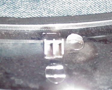
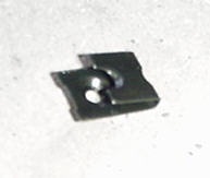
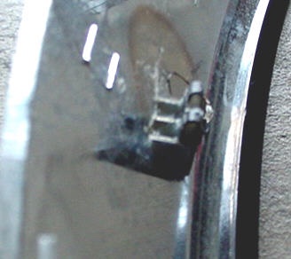
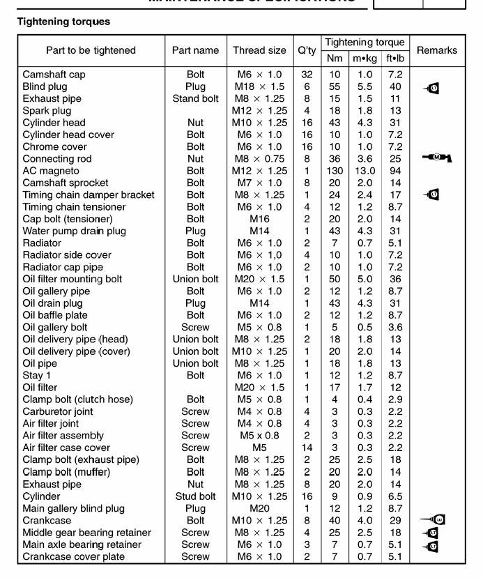
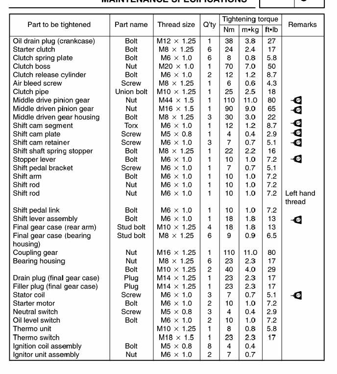
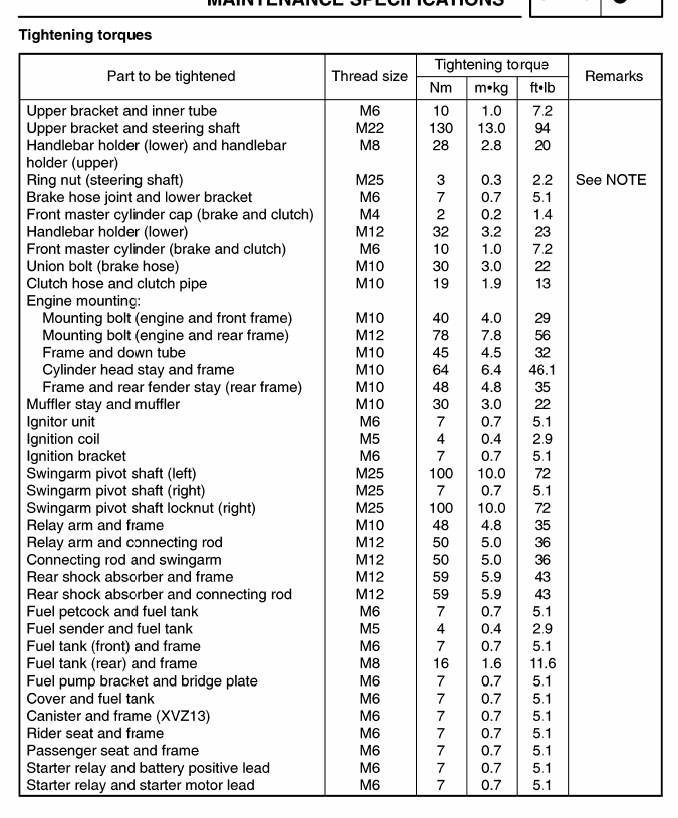
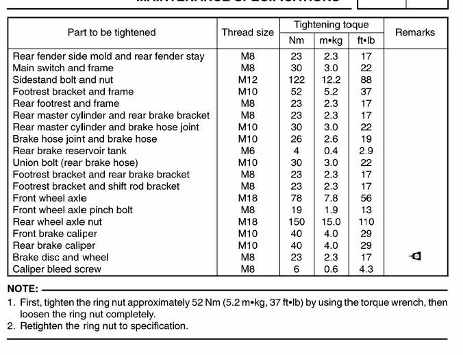


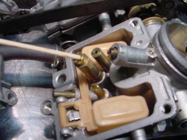

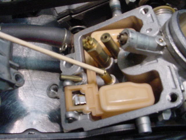
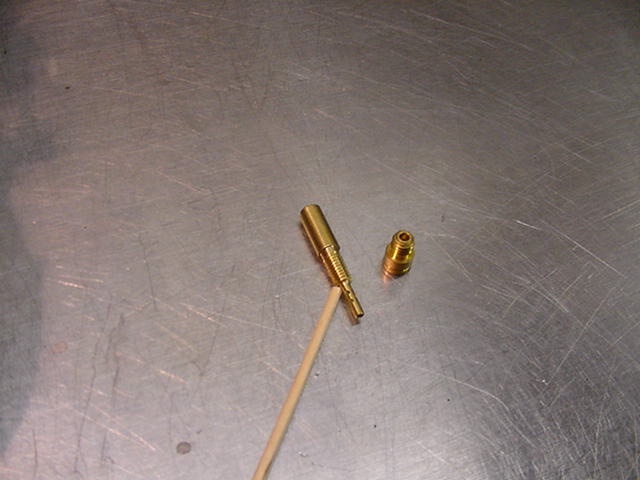
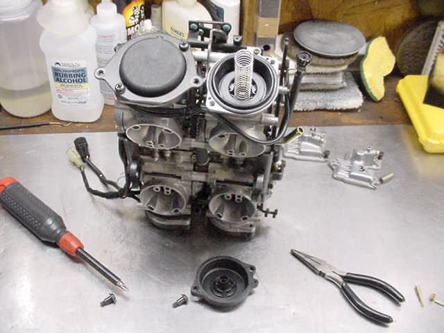
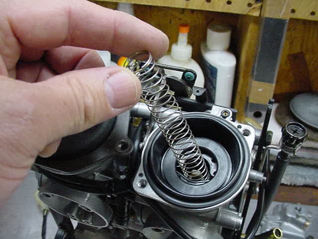
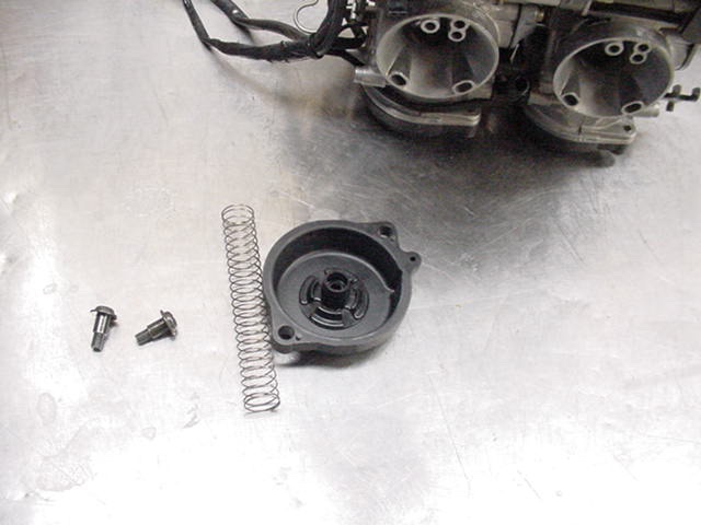

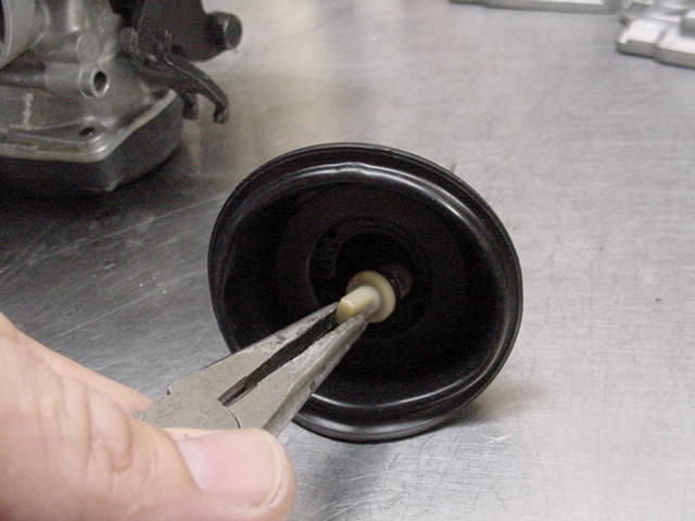
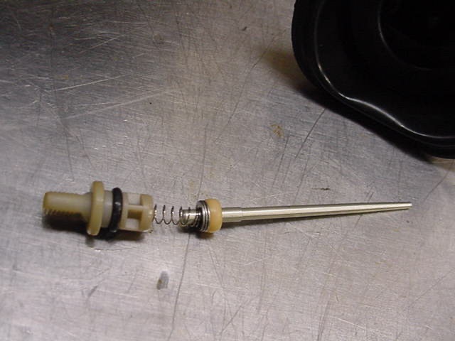
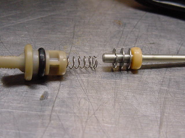
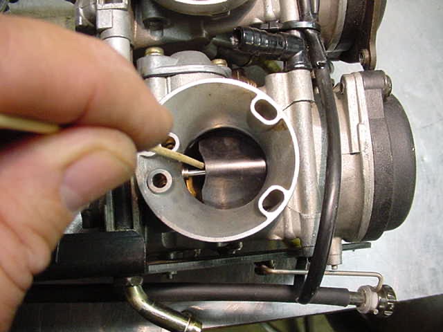


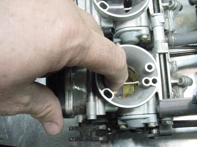
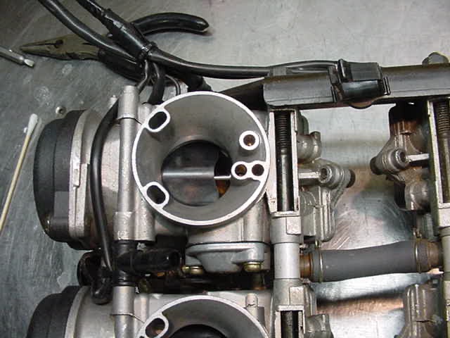
 Jetting is NOT an exact science and unfortunately, it sometimes takes two or three tries to get things the way you want them. Is it worth all the trouble? I don't honestly know....if you try this, maybe you can tell us.
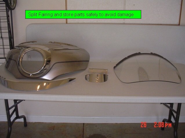
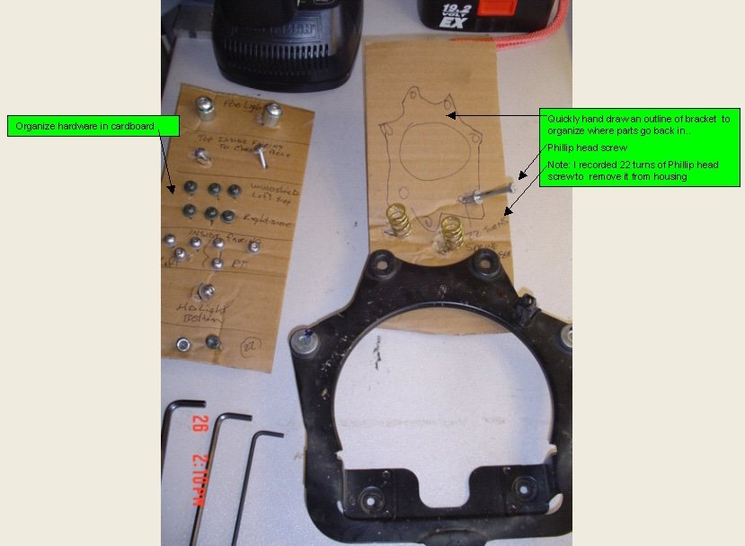
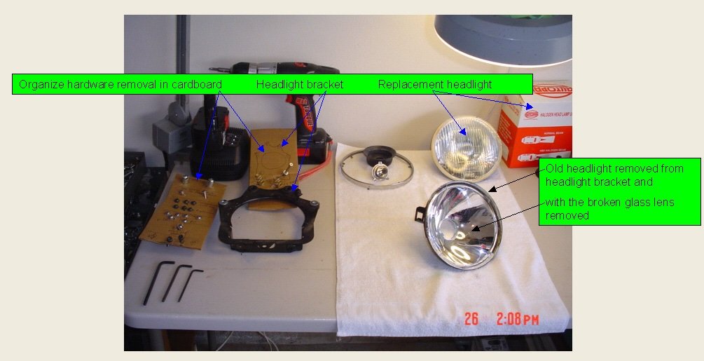
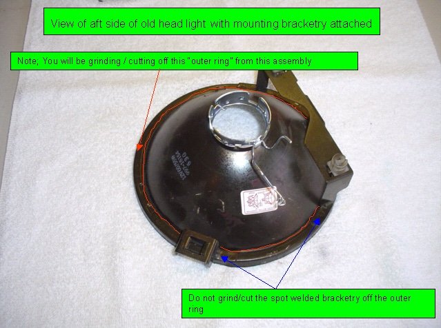
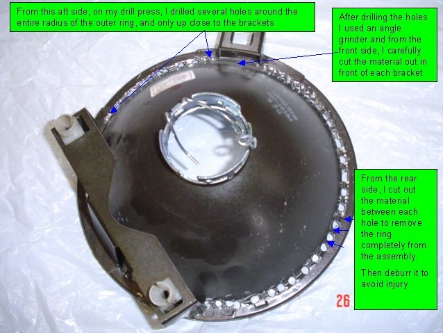
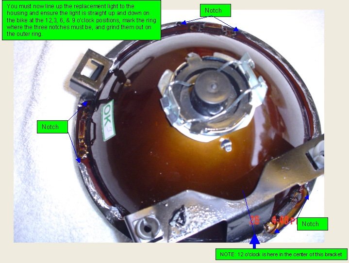
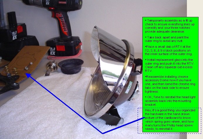
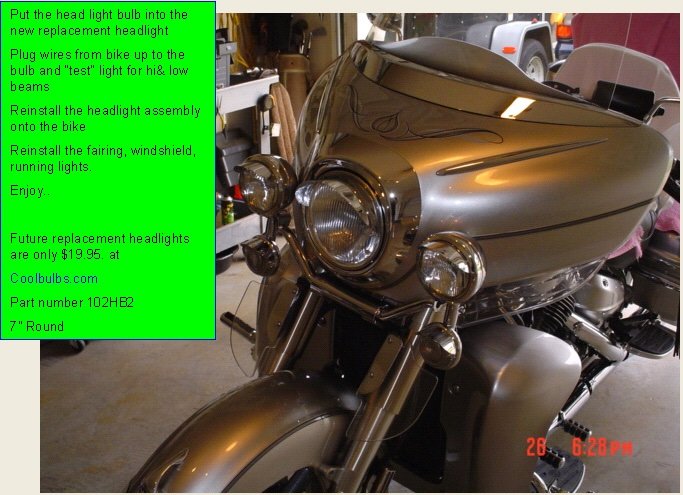
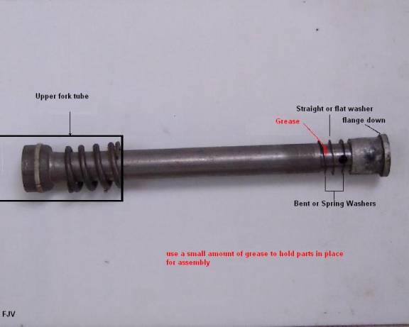
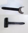
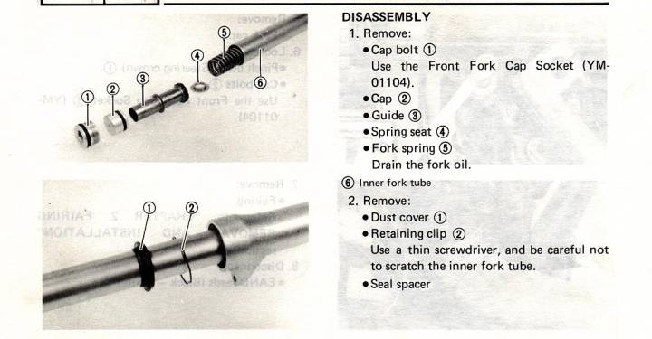
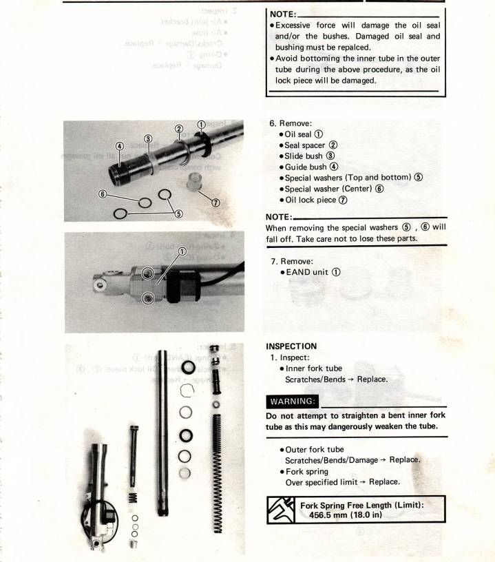
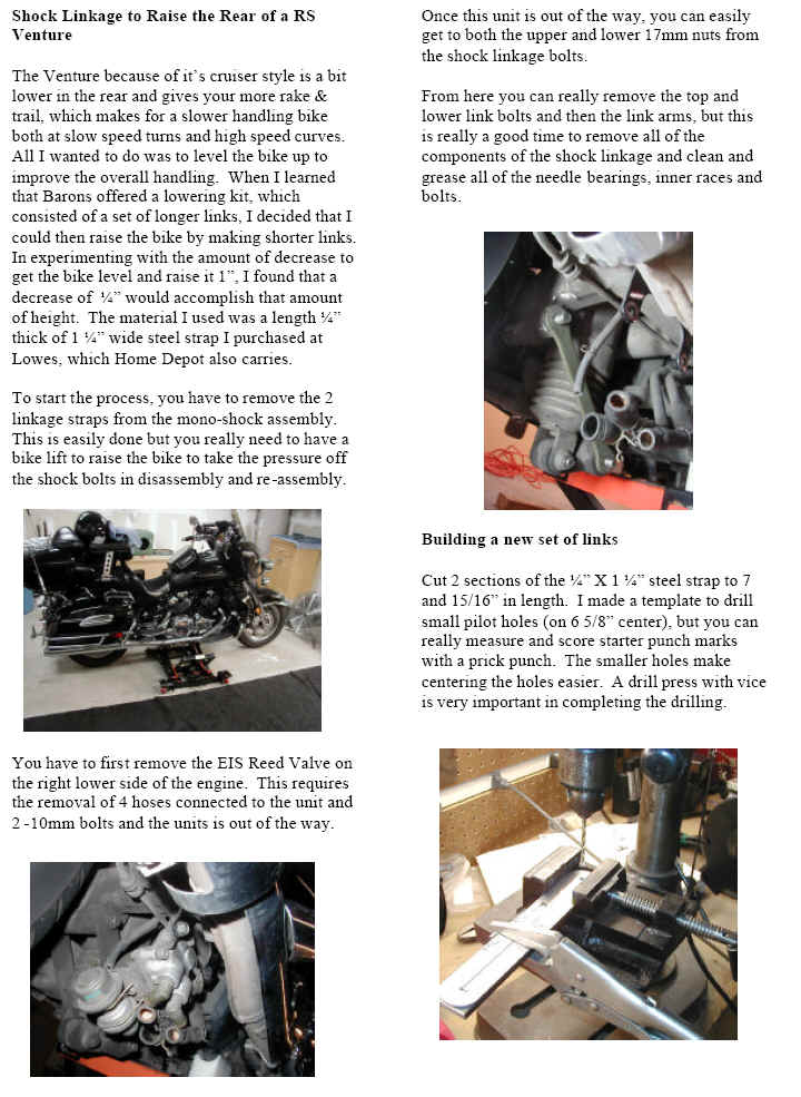
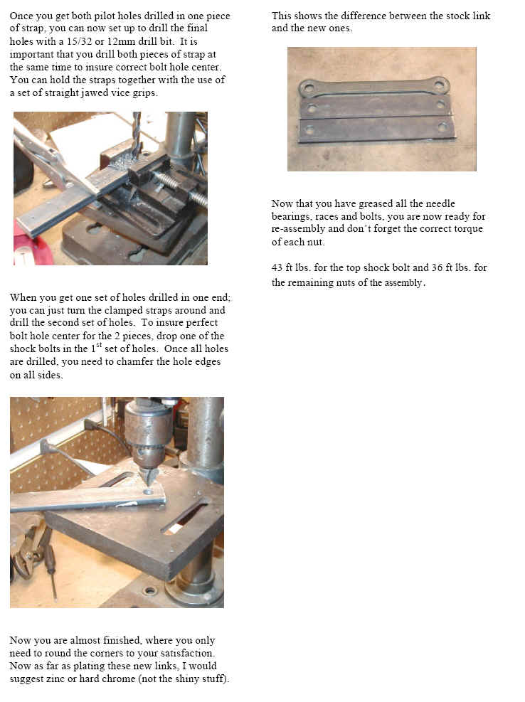
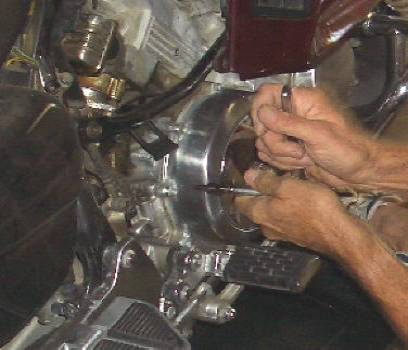
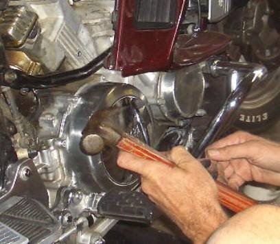
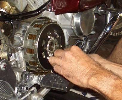
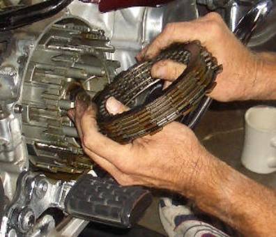
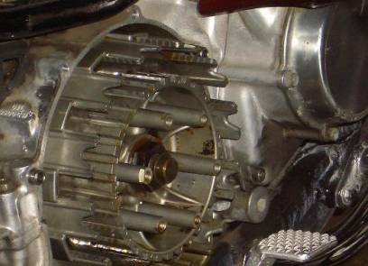

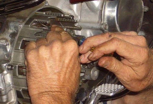
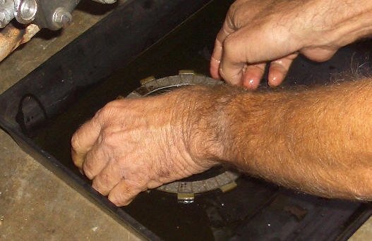
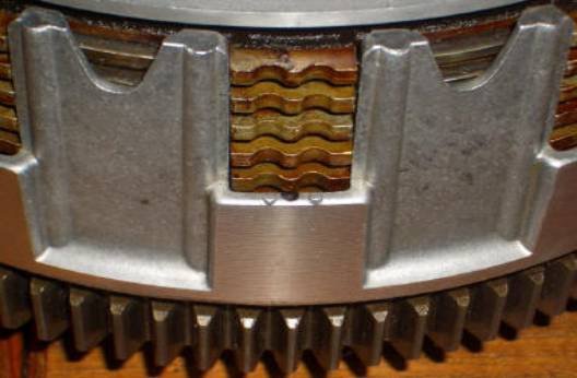
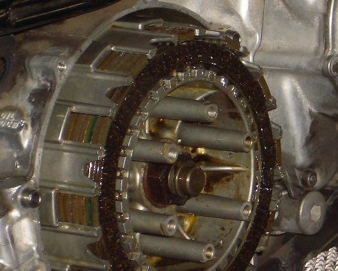
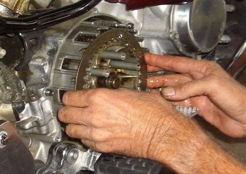
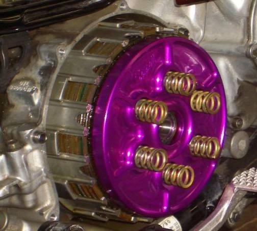
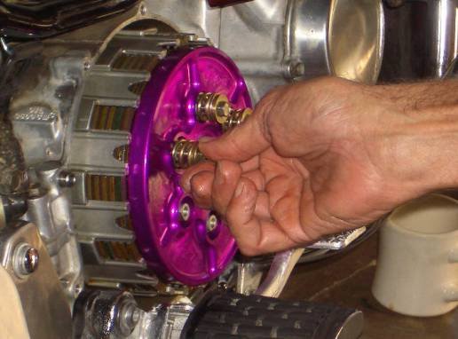
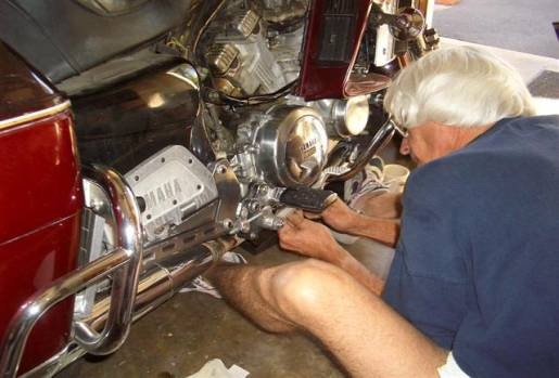
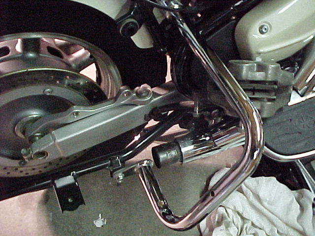
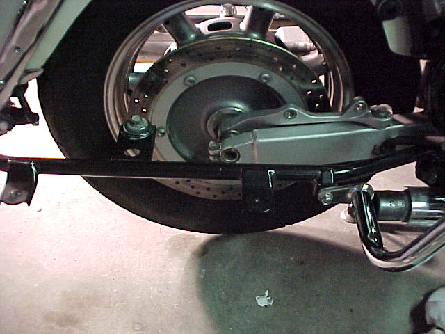
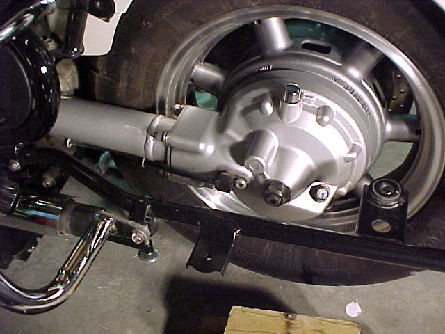
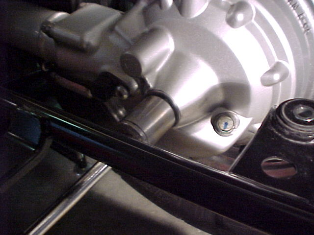
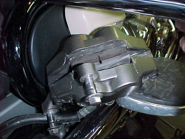
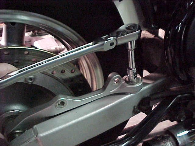
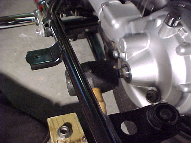
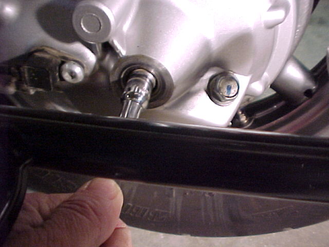
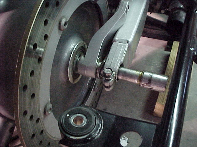
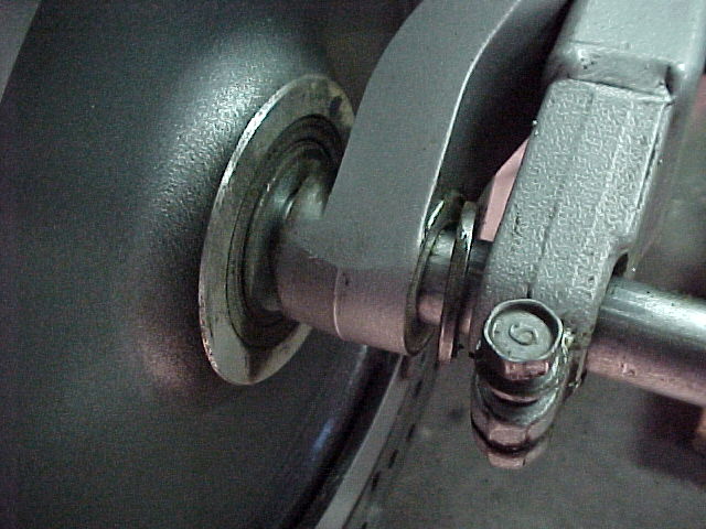
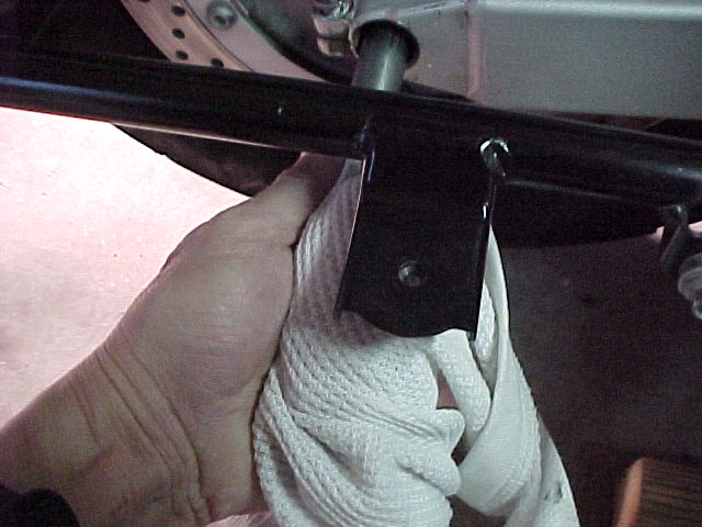
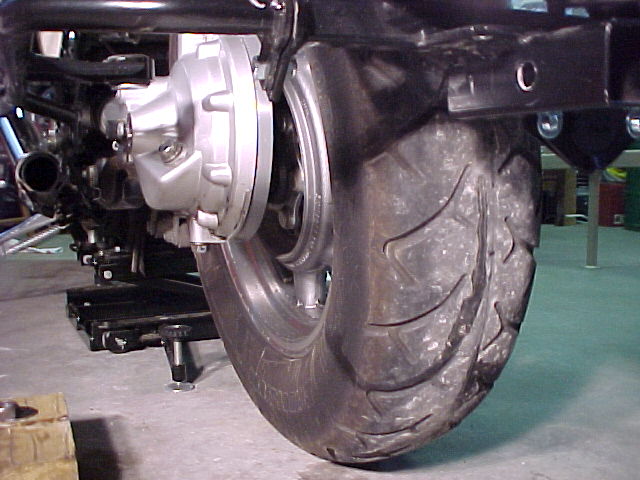
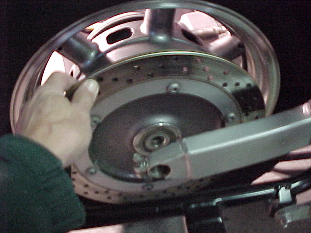
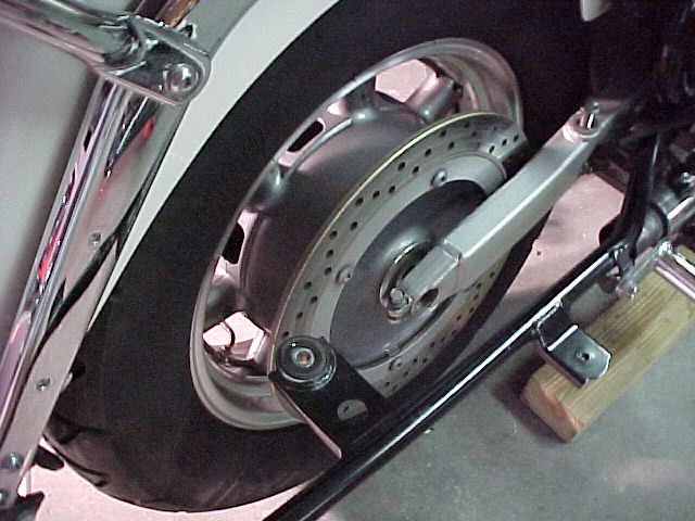
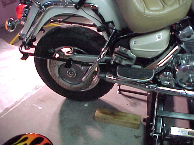
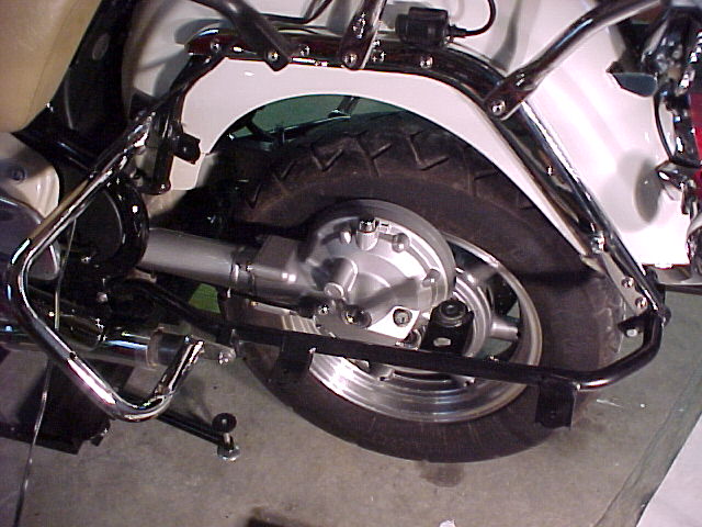
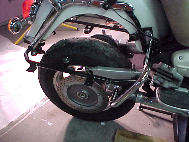
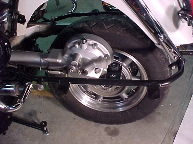
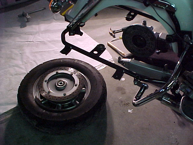
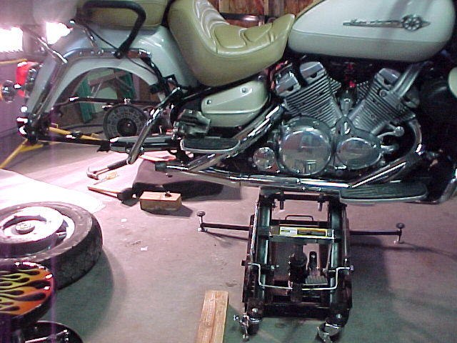
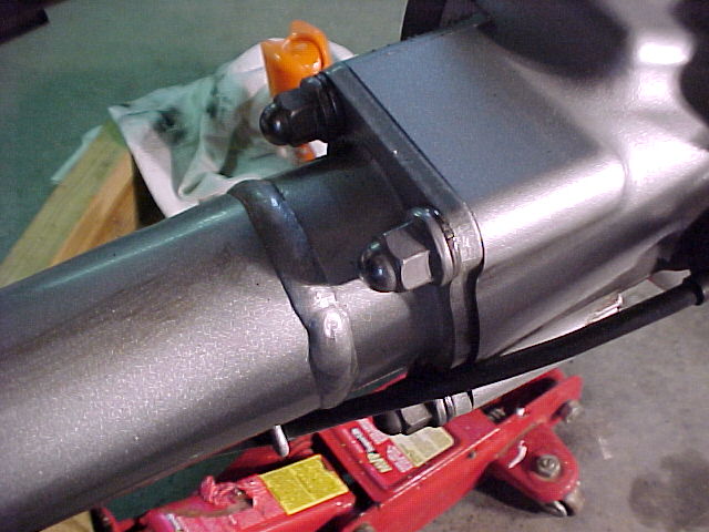
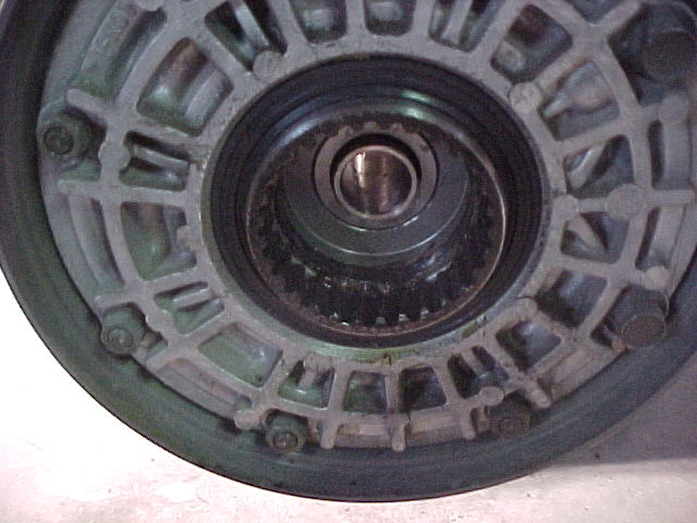
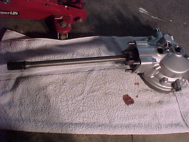
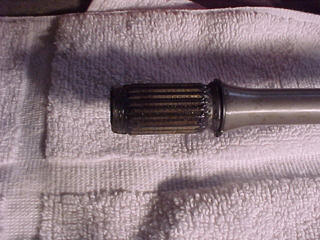
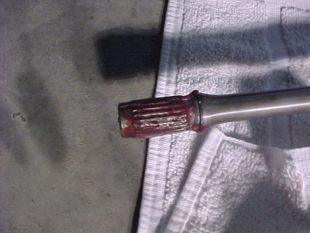
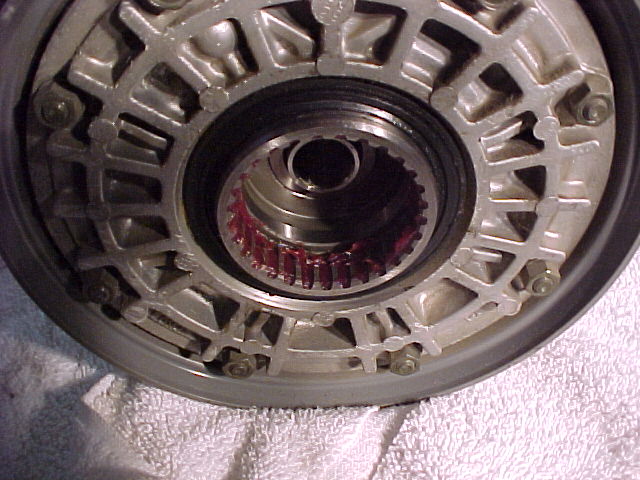
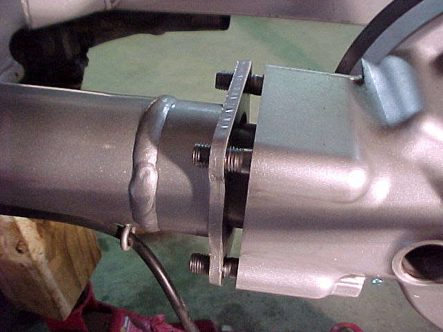
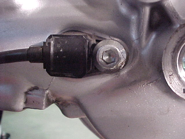
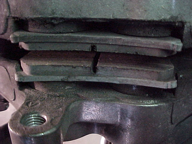
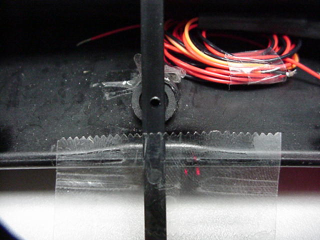
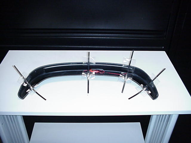
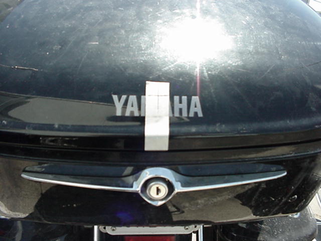
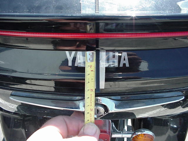
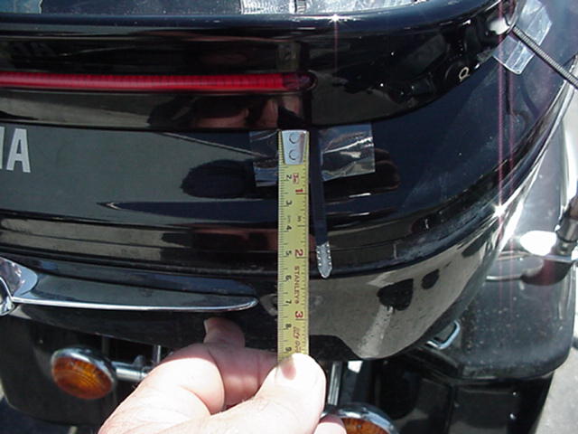
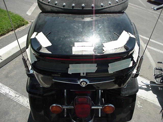
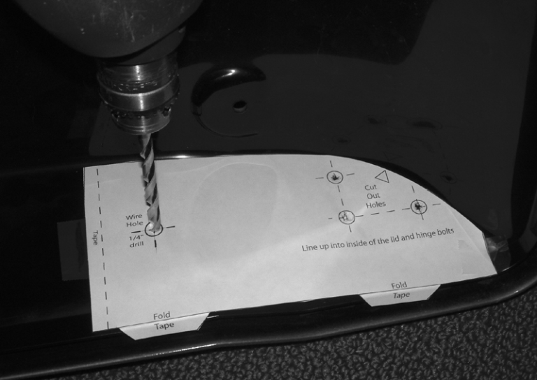
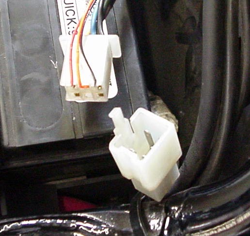
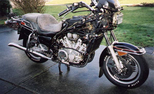
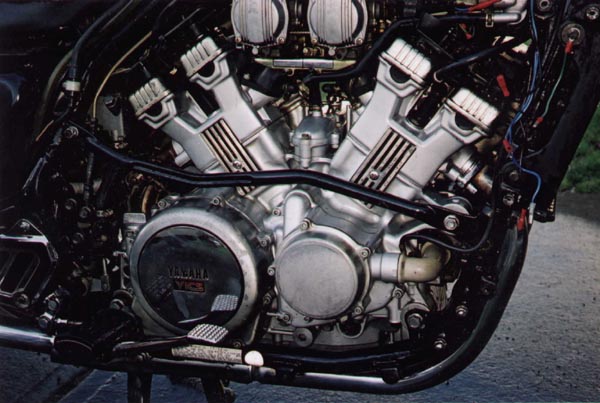
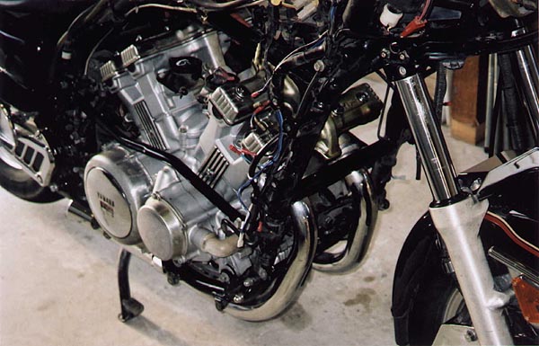
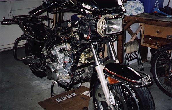
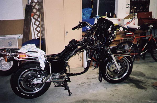
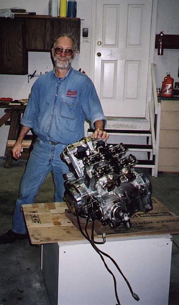
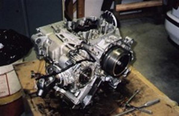
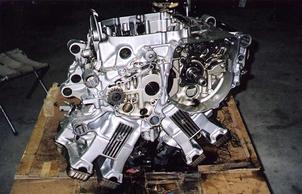
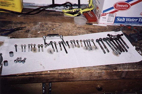
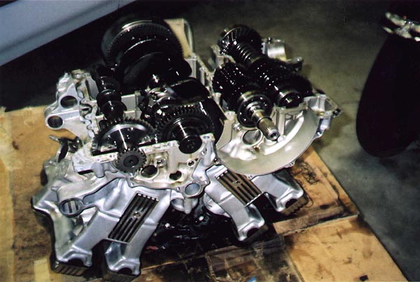
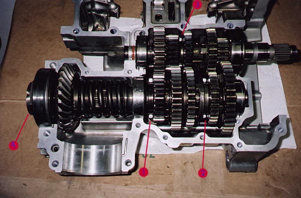
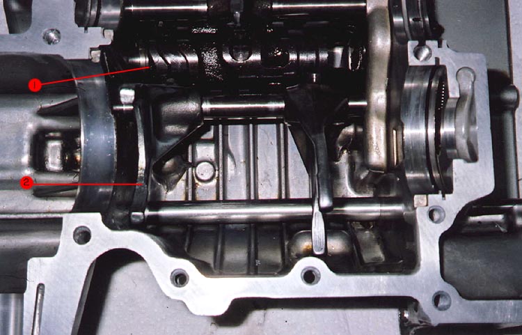
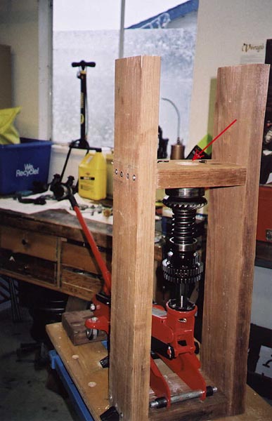
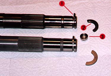
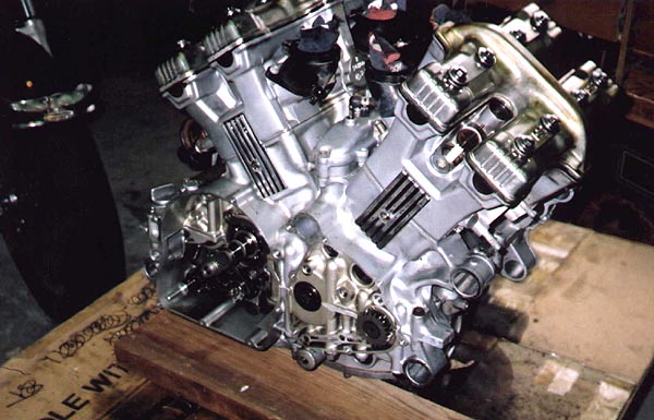
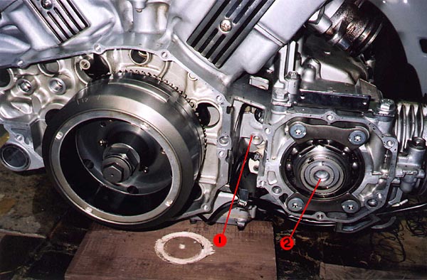
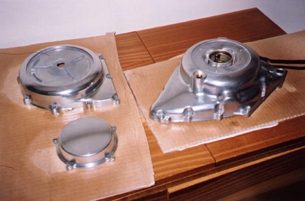
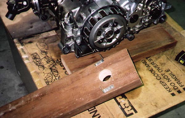
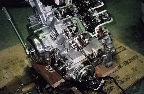
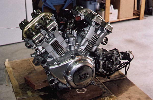
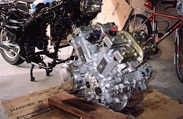
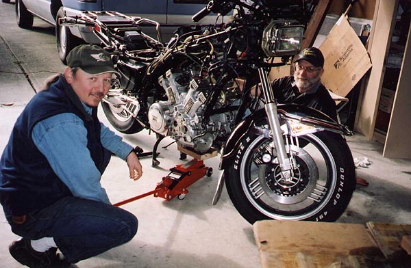
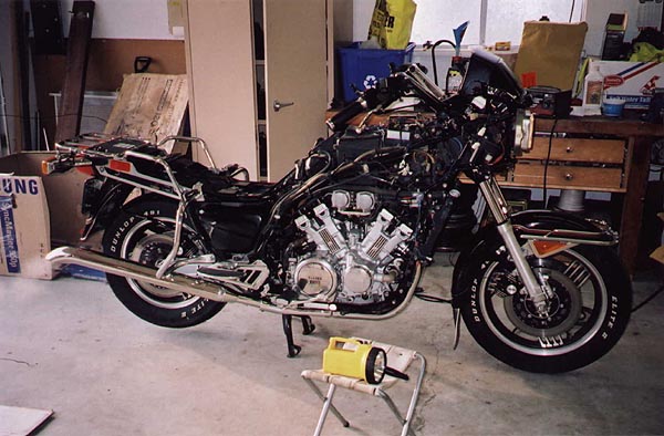
Oil Filters
in General Tech Library - READ ONLY!
Posted · Edited by Freebird
For a LOT of other good information, please visit his site at:
California Scientific
http://www.calsci.com/motorcycleinfo/FilterXRef.html