Search the Community
Showing results for tags 'wire'.
-
 Need Advise: My parts source in Puyallup Wa did not have the Hazard SW nor the 41R Relay. So I'm into the wires. My turn signal and 4 way flashers are not working. I've cleaned all the related connectors and clean and tested the bulbs and sockets. 1) At the hazard sw connector the Bike side. When I turn the key on, I get power to the RED wire & Tan wire. When I use the turn signal for both turns still on the RED and TAN wires has power. Now I put the Hazard wire plug into the Bike end of the Hazard plug. 2) On the Hazard SW side of the plug the RED & TAN wires still has power. Inaddition the TAN/YELLOW wire now has power. Same when the Hazard SW is eithor ON or OFF. Nothing changes when I use the turn signals. 3) If I put the Hazard SW right in the middle of the OFF & ON, the TAN/YELLOW wire no longer has power. Just wondering what it would do. My knowledge of wireing is pretty basic. From this point I do not know what else to test for power. Any Suggestion.
 -
Does anyone know where I might find or order the right side wire guide that also holds the front reflector? I've looked in my manual and it can't find a part number so going on line to order one doesn't seem to be an option without it. Repair Ideas Also Welcome!
-
Of course I forgot the lock in the front wheel, put her on the side and destroyed my speedo wire...unbelivable. Does anyone know which speedo wires work on our bikes from other models? Looked for XVZ1300TD and could find none but plenty for other Yamahas, should fit anyhow I guess but which ones?
-

diamone r led light question
david Taylor posted a topic in Royal Star Venture Tech Talk ('99 - '13)
I recentlyh purchased the Led slimline light from Daimond R. I'm not very elecrically oriented and I can't tell how to wire it. they recommend under the seat but I can't tell what wires are what. it comes with a brown and green wire, do I connect it to the brown and green wire under the seat. I also just installed the 100 led light from custom dynamic. I'm assuming this isn't too much current for the bike. any help to my ignorance would be apprecaited. thanks David. -
 I have my bike all torn apart, gas tank removed, faring parted. But I can't find the red wire with a yellow stripe on it anywhere to save my life. Here is a picture of the wires that are outside the harness. The first picture shows no red wires. The second picture shows a neutral coloured connector with one red wire with a yellow stripe in it. This is the only red/yellow wire I can see anywhere. Could someone please confirm if this is the correct wire to tap into in order to have my driving lights on at all times? Thank you in advance Chris in Red Deer, Alberta
 -
 I am trying to figure out the wire size for the rear lights.... I think they are 16 gauge..... Just want to make sure I get the correct fittings for tying in the Hoppy isolator Thanks, Robert C.
 -

Just saw this new recall..... June 2011
Guest posted a topic in Royal Star Venture Tech Talk ('99 - '13)
Vehicle Make / Model: Model Year(s): YAMAHA / FJR1300 2006-2009 Manufacturer: YAMAHA MOTOR CORPORATION, USA Mfr's Report Date: JUN 24, 2011 NHTSA CAMPAIGN ID Number: 11V338000 NHTSA Action Number: N/A Component: ELECTRICAL SYSTEM:WIRING Potential Number of Units Affected: 9,850 Summary: YAMAHA IS RECALLING CERTAIN MODEL YEAR 2006-2009 FJR1300 MOTORCYCLES MANUFACTURED FROM FEBRUARY 2006, THROUGH MARCH 2009. THE GROUND JOINT CONNECTOR OF THE WIRE HARNESS COULD OVERHEAT AND BECOME DEFORMED, POSSIBLY CAUSING AN INTERMITTENT GROUND WIRE CONNECTION. IF THE ELECTRICAL SYSTEM IS NOT PROPERLY GROUNDED, THE IGNITION SYSTEM AND/OR OTHER ELECTRICAL COMPONENTS COULD MALFUNCTION, WHICH COULD CAUSE THE ENGINE TO STALL. Consequence: IF THE MOTORCYCLE STALLS WHILE BEING RIDDEN, THERE COULD BE A CRASH RESULTING IN INJURY OR DEATH. Remedy: YAMAHA DEALER WILL INSTALL AN ADDITIONAL WIRE SUB-LEAD OR, IF THE GROUND JOINT CONNECTOR HAS ALREADY BEEN DAMAGED FROM OVERHEATING, DEALERS WILL INSTALL A NEW MAIN WIRE HARNESS. THIS SERVICE WILL BE PERFORMED FREE OF CHARGE. THE SAFETY RECALL IS EXPECTED TO BEGIN DURING JULY 2011. OWNERS MAY CONTACT YAMAHA AT 1-800-962-7926. Notes: OWNERS MAY ALSO CONTACT THE NATIONAL HIGHWAY TRAFFIC SAFETY ADMINISTRATION'S VEHICLE SAFETY HOTLINE AT 1-888-327-4236 (TTY 1-800-424-9153), OR GO TO http://HTTP://WWW.SAFERCAR.GOV . -
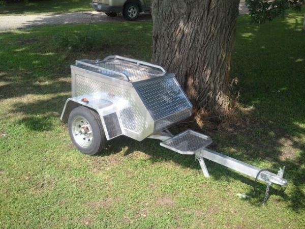
Finally got a chance to pic up our trailer. Its an 02 Aluma MCT. We've been looking to add one and were able to find this one 50 miles from home at 2/3 what the dealers wanted for them. Just need to get a hitch and wire the Venture and were ready to roll. The wife can't wait. Now she can pack the essentials like extra shoe's!

-
The only thing I have left to do is get this dang trailer wired up before leaving for Cody. If anyone could pop the passenger seat off their bike and take a pic of their wiring it would sure help a bunch. I have a Motorvation trailer that has a 5 wire setup directly from the factory so I don't think I need any type of converter, and I do have the RSV wire color chart. Has anyone wired a 5 to 5 wire?? Another thing I'm runing into is the wire guage at the 6 way plug under the seat. Looks like 18ga on my '99, but yet when I get behind the brake light the wires are the more larger 14ga size. Yes, I did look behind the light just to see what was available. I just thought a pic would help me a bunch.... Any help would be appreciated.
-
It's not a Venture but I am hoping someone has experience with these bikes. The problem; The battery goes dead and the engine dies. It happens faster if the headlight is on. The system. 1971 Honda SL125. A 6 volt balanced charging system (rectifier but no regulator). It has a four wire rectifier. Two from the stator, one battery neg and one battery pos. it has a two step 3 wire stator. White stator wire goes to headlight switch and activates second step of stator and is switched to the yellow wire when the headlight is on. The yellow wire, first step, goes to the rectifier. The pink wire goes to the rectifier and is common to the white and yellow. What we have done: We resistance checked the stator. Leg 1-0.3 ohm Leg 2-1.7 ohm. No continuity to ground. AC output out of stator leg 1 7.5 to 9.5 volts AC at rectifier. Leg 2 7.5 to 9.5 volts AC at rectifier. Diode check rectifier front .350 volts to energize, back open on all 4 diodes. Disassemble selenium rectifier and clean all connections just in case. Perform voltage drop on positive and ground wires to the battery. Resolution. The problem is not resolved. We have 6.3 volts 0.1 to 0.9 amp at the battery running and 5.91 volts and falling with -2.1 amp with the headlight on. Questions: Is stator resistance ok? Honda does not publish a spec. Is stator AC output voltage 8-9 volts ok for a 6 volt balanced system? Can the rectifier diodes test good and it still be bad? Any ideas? Plan; Our current plan is to wire in a rectifier from an automobile alternator and see what happens. Anything else we can try? Thanks Mike
-
"Yamaha Motor Corp. is recalling certain FJR 1300s due to defects in the vehicles’ electrical systems. The potential number of vehicles affected is 9,850. FJR 1300s manufactured from February 2006 through March 2009 could have potential issues with ground joint connectors. The company says that the ground joint connector of the wire harness can overheat, become deformed, and possibly lead to malfunctioning ignition systems and other electrical components. Yamaha dealers are being asked to install an additional wire sub-lead or install a new main wire harness free of charge. For more information, call Yamaha at 800-962-7926." Rut row. Not good.
-
Hi folks, I've been tracking a charging problem on my machine and using the electrosport troubleshooter I believe I have the problem identified. As I see it, the brown wire on the R/R is an input to the unit and should supply system voltage to the R/R. It reads low on mine at the connector nearest the R/R. In my belief, connectors, then switches are more likely than wire to create voltage drops. The connector nearest the R/R checks OK in that voltage is the same on both sides (LOW). Where else should I look / test? Other connectors in the signal circuit to the R/R? How do I test out the ign switch? The other fix could be a later R/R with an internal sensing that would not rely on the brown wire to monitor voltage. I believe the Shindengen unit is like this. What is the list wisdom on this. The Electrosport guide indicates this is the hardest fault to find and, honestly, I need a hand. Everything I wrote above could be wrong, I'm building my Venture charging knowledge up even as I post this. Thanks in advance!
-
 I have determined by testing and using a jumper wire that my 83 VR has a bad wire from the switch to the first junction behind the headlight. Running a second wire is no big deal but wanting to do a good job of it, how do you get the switch out of the casting for the master cylinder/lever. I have taken the "bracket" loose and everything is good to pull the little section of old wires out but it appears that the wires do not unplug from the switch and I need to get the swith out to have a better look (switch shows as part number four on the parts breakdown and is part number 26H-83980-00-00 - sells for about $35.00) Any help? Steve Neal
 -
I was given some nice LED lights. One of the features is the ability to have them come on with a signal wire, even if off. I set them to the mode I want (e.g., flashing yellow), then turn them off. When I pull the brake lever, they come on flashing yellow, then turn off again when I release the brake. Or they should. They do come on with the brakes, but they also come on with the turn signals. The lights come with a red for power, off for ground. They also come with a blue for aux signal and yellow for ground. I have red to battery, black to ground. Blue to the yellow brake wire, yellow to ground. Should I attach the yellow to the brake ground? Is that brown, if I remember right? I don't mind the LEDs coming on with the turn signal for now, but it isn't what I intended. Dave
-
My HID headlight came in Friday, from Canadian Custom Got out yesterday afternoon and installed it. The hardest part was getting the HID bulb in to the headlight bucket. I had to take the two bolts holding the frame in place, out, to get that long bulb installed. (note to self don't forget the rubber seal ring around the back of bucket!!!). Then where to mount the power supply? Well there is an empty flat place (looking AT the bike) on the left. Thinking double sided emblem mounting tape, but not sure of the heat. Really don't wanna drill holes in the fairing, so lemme call the expert! I guess great minds run in the same circles (Thanks Squid!!!). So I mounted it with the tape right in that spot. Since I already have a "fused" power wire run from the battery to a switch (that picture did not turn out) all I had to do was connect the large power supply wire for the HID light to that switch. Woo Hoo didn't have to pull the tank!!! I did run in to one "bump in the road", the red power supply wire pulled out of the fuse holder (insufficient crimping) that is supplied with the light kit. A quick trip to Autozone and that was taken care of. MAN, that sucker is BRIGHT!!! The pictures don't show it, but it makes the stock passing light bulbs look like yellow fog lights:(.
-
It seems that some of the Saturns are plagued with horn button failure. It sticks closed, thus the horn blows continuiously. Well I am lucky enough to have bought a 2003 Vue with this malady. The problem is that the horn "button" is part of the $700.00 air bag. As you can guess I ain't gonna replace the airbag. I have found a schematic that shows a black and a black/white wire on the dash side of the steering column, which I wish to intercept. That way I can put a $2.50 "Rat-Shack" push button on the dash. Well I have cut in to the red wire in the airbag, which when grounded makes the horn blow. My problem is that I have checked EVERY wire under the steering column cover between the clock spring and the dash. NONE is common to the red wire in the air bag. as a temporary fix I have wired the switch to the red wire in the air bag and left it hanging out from under the air bag cover. Pray tell, do any of you know where the #28 wire is to be found going down the steering column?
-
Here are a few pic's of the new trailer. Have not taken her down the road yet, as I need to license it and install a hitch on the RSV(coming soon). Adjustments are, added 25" to the tonge, flipped the axle over and raised the fenders, added tie down anchors, and built a tonge stand. Now, what ALL do I need for my RSV,too wire it properly to the flat 4-wire harness on the trailer. Is some type of wire converter all I need? After reading through a few posts, I'm a little confused (my life story). Thanks to all that have built a trailer and passed great tips/knowledge on to us. Happy Easter! Byron
-
I have to enter this thread since my initial thread. I want to respond to some of the comments generated concerning the install of my Buckeye Performance high output stator install. First, I need to qualify something. My son-in-law did the install. He is a 15 year journeyman mechanic both heavy duty and automotive. In other words, he is a professional in his trade not a backyard mechanic. He did not cut out the connector and hard wire the new stator. My new stator will not leak contrary to all those who said it will. My son-in-law used professional grade material from his shop that in his career he has used countless times. In his fifteen years as a mechanic he has installed probably hundreds if not thousands of stators, alternators and every conceivable type of component found in an electrical charging system. He currently works in an agricultural shop working on tractors, combines, and diesel farm trucks of every description. I have been told that the connector is the weak link. That if you don't hard wire the stator your bike may catch fire and burn. Why is that? I have been told to use 12 gauge or even 10 gauge wire when I hard wire the stator. Why would that be? So here is my answer to all of that. I asked my son-in-law if there was a problem with retaining the connector. He said no. He said that $750,000.00 farm tractors putting out 185amps run it all through an identical little plastic connector. My car's charging system and all trucks cars, tractors, combines etc. all run their power systems through identical plastic connectors. I then asked him in his 15 years as a professional mechanic if he has ever in a manual, workshop, training seminar, or classroom ever seen a big red warning that states something to the effect, "WARNING! IF YOU CHANGE THE STATOR IN THIS TRACTOR, CAR, TRUCK, COMBINE, MOTORCYCLE YOU MUST REMOVE ALL CONNECTORS AND HARD WIRE THE NEW STATOR OR YOUR $750,000.00 TRACTOR, CAR, TRUCK, COMBINE OR MOTORCYCLE WILL BLOW UP AND BURN! He has never in his 15 years as a mechanic seen such a warning. Here is the thing. The wire harness on the OEM stator and on the Buckeye Performance high output stator is 14 gauge wire, not 12 or 10 gauge. If you install 12 or 10 gauge wire in your installation then yes, the probability is good that your new stator will possibly burn. My question is on what premise? Because by inserting a larger gauge wire the 14 gauge wire that is still in the circuit cannot now handle the increased amperage flow from the larger diameter wire and it becomes a weak point or choke point that can potentially cause a fire. The only way the connector will be a problem is if the connector has rust or corrosion built up on the inside. Why is that? Because the rust or corrosion acts as an insulator and the increased amperage can cause it to heat up and possibly catch fire and or melt. If the connector is clean, and free of rust or corrosion it will not present a problem. If it is dirty, rusty or corroded then all you have to do is install a new connector. I do not believe that my connector will not burn or melt. Someone mentioned about the position of the connector, that, and I quote, "Well, when these bikes are assembled you can't really tell where the parts might be because they are all assembled differently and there is no way to tell where the components might be placed." When I sat down and thought about that, I thought it was an odd statement unless I totally misunderstood the reason behind the remark. It left me with the impression that these bikes are assembled randomly by 8 year old, blind drug addicts in a chop shop by throwing parts into the air and seeing where they attach themselves to the frame. To each there own. But I had to comment on all the comments about my stator install burning up and/or failing. I don't think it will fail based on what my son-in-law told me and the work he did. If it does fail, I will be sure to post it as a follow up. But I will also post at the end of the riding season so far so good. Chris in Red Deer, Alberta
-
 Hello All. Thanks for taking a look. Little history first, 83 VR. Less thank 6k miles. New to me. Has spent the better part of its life sitting in a yard. So far, I have: Pressure washed Full carb overhaul Bleed the clutch Re soldered the CLASS thingy Changed spark plugs Checked gas tank for rust Some other odds and ends not related After getting my carbs finally done. Put em back on and it ran. Much improved than before. I have not synced yet. The tach is non responsive. I rev it up. It goes down. Let off it goes back up. Thought it was strange. Bike will not rev up past *k RPM. I do know that #1 is getting a spark when I push the starter button. Then as soon as it starts, the spark goes away. Of coarse I am letting off the button when it does start. However, if I tap the button while it is running I can see it get a spark. I know I should not do that. But it was a thought. If I hit the kill switch, I can see a weak spark. If I turn the IGN. switch off, I swear I see a weak spark again. I have checked the plug cap. It was clean. The place it mates with the wire was slightly corroded and loose. I have since cut off till I got good wire and reinstalled with no effect. As I type this its 26*. Its a bit cold to go dealing with it much. I have not checked out anything else. I plan to take the right hand controls apart and clean it. I also plan to check out the fuse holder on the bat. What else should I look at? And how should I do it? I was under the impression that coils either work, or dont. Is it safe to assume that? If she needs a new TCI, I will have to move on. I do not want to give up that easy, but buying a used on on eBay looks out of the picture. Michael
 -
Opinions on this... I have : - passing lights (relay to battery, on/off switch on fairing) - Stebel Horn w/bracket and wiring harness with relay - 5 to 4 wiring converter/isolator (Reese - requires power) - trunk wing (doesn't require power but wiring is in there too) Connecting the bike's positive power cable plus 3 others and it was getting pretty messy on the battery post. Couldn't find a small enough (and covered) "power bar" so I kind of made my own. Used 16 gauge wire with eyes/rings on both ends and slipped it and the other wires (with eyes/rings) onto a bolt and put a nut on it to hold it secure (you can see it sitting on top of the battery wrapped in electrical tape). Each accessory using power is fused. I figure the 16 gauge wire from the battery should be enough to carry the load from the three devices requiring power. This a good way to do it or bad? Comments?
-
Will be putting it together this weekend. I've read of the trials and tribulations some have had with them, so I'll be paying close attention during assembly. I'd like to add the Wally World (about $35.00) led trailer taillights. I'll also be adding a 5 wire in to 4 wire harness. question is how will the bike's turn signal function react to these additions? Time permitting, before Kreg's MD I may add these running lights. http://cgi.ebay.com/ebaymotors/LED-Red-boat-motorcycle-truck-trailer-RV-light-99HBR-_W0QQcmdZViewItemQQhashZitem53e659df3aQQitemZ360346935098QQptZOtherQ5fVehicleQ5fParts
-
i am going to replace the old "glass fuse" block with spade type fuses. my question is "are all circuits energized by one main positive wire, or are there different power inputs from other circuits, that energize a certain fuse"? just jt:confused24:
-
 I installed the LED amber front marker lights on two RSV thus far using this method and it works great.. The lights you get from JP Cycles have a black and yellow wire.. the power wire is yellow and looks terrible when running up the brake cable.. So what I do is snip the black wire (ground) and solder it to the snipped yellow wire, heat shrink covers the joint and the short yellow wire end. The ground wire gets an eye end connector which I then connect to the attachment bolt for ground. The new power wire, now black, gets routed up the brake hose and wired into the system.. works like a charm. There might be easier better ways of doing it, but this works for me.. However, on the last bike I did this to, one marker light wouldn't lite up so before automatically assuming I had a bad or cold solder joint, I tried touching the ground to different bare metal parts on the bike and sure enough.. that was the problem.. Strange indeed.. on that particular bike, the lower fork wasn't grounded at all.. I literally had to run a ground wire up higher onto the upper tree area to ground the light.. Any bare metal exposed on the lower end wouldn't give me ground.. Just happened that all the attaching parts were shielded with a good layer of paint at assembly time..
 -
I am thinking of adding the Kuryakyn RTB module to my 2005 RSTD.... I do not have an owners manual and the one i downloaded doesn't appear to have the wire colors for the brake and turn signals on the rear... Does anyone know where I can find this information?? Thanks, Robert C.
-
I have this little black box hooked into my headlight wires. It is an obvious aftermarket, or add on. It simple is a 2 wire little black something with no name on it, the two wires go from this llittle box to the ground and I think high beam power wire at the headlight. It has scotch lock style fasteners so I know it is not factory. Just cannot imagine how something that has nothing but 2 wires coming out of it "tagged onto" the headlight wires does anything, but I know its not put there for looks LOL Again the headlight wires are NOT cut and this thing put in as something the power is running through, it is simply tagged into the wires by use of scotchlocks which I do not like.