Search the Community
Showing results for tags 'remove'.
-
"Venturedad" vs. "Vertical Hide a Hitch by Cheyenne Trailers" on the diamond r website. Has anybody installed the hidden hitch and how hard is the stinger to remove?
-
Does anyone know if the rubber on the passenger floorboard is removable? Want to remove to get the floorboard back plate chromed, then reinstall the rubber.
-
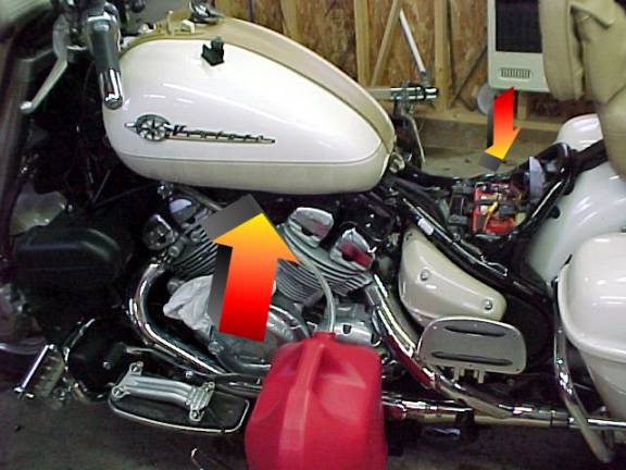
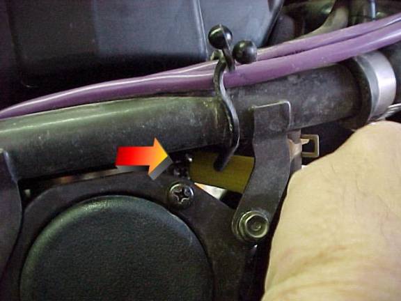
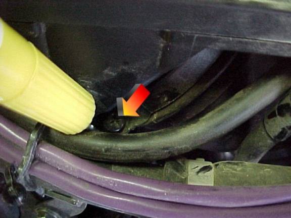
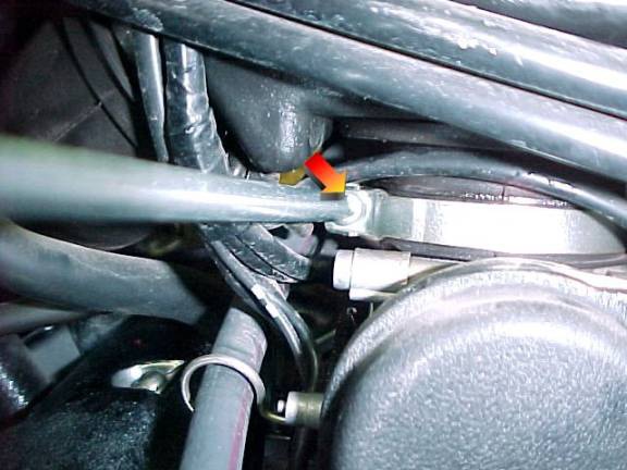
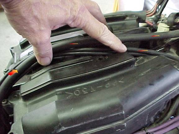
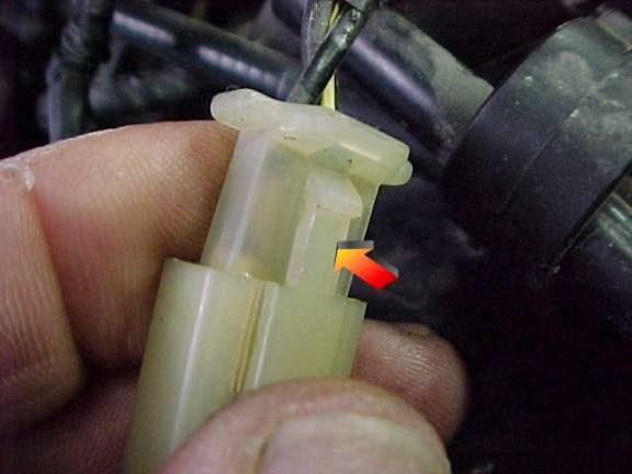
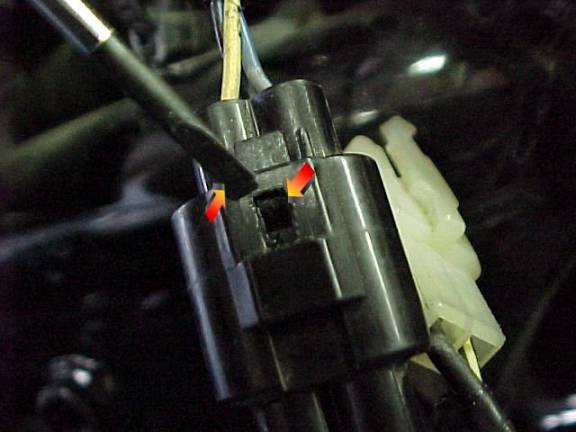
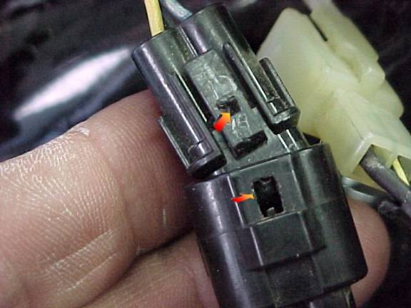
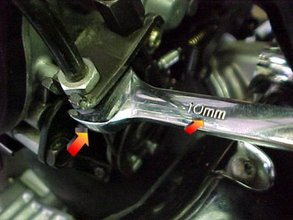
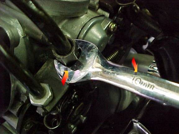
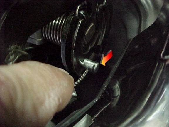
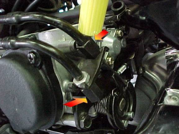
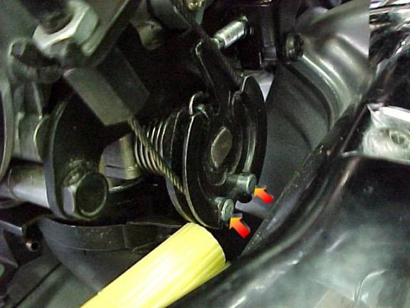
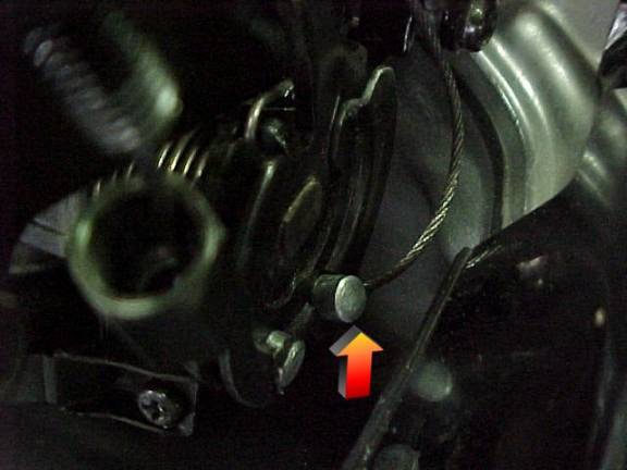
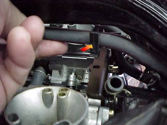
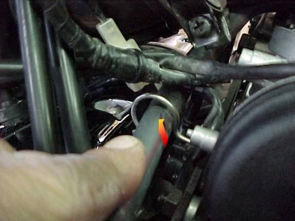
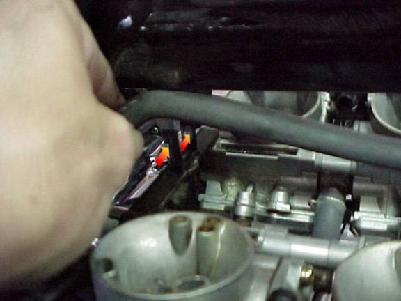
Installing a Dyna 3000 module in a Royal Star Venture Thanks to Scott (Tartan Terror) for this great article. Remove seat form bike. After you do this you will need to remove the battery. Remove the cables first then remove the strap hold down. Be careful not to touch terminals together or they may spark. Also be careful to make note of where any accessory wires you have installed are routed. http://www.venturerider.org/dyna/image002.jpg http://www.venturerider.org/dyna/image004.jpg Remove the battery tray next. You will need to remove the two 12 mm bolts in front of the tray. Remove the positive and negative wires from the clips that hold them and gently lift the tray out of the way. For those of you that have other items behind the tray be careful not to pull that out and lift the tray out. With the tray out of the way you will see the module standing vertical held by two nuts against the front wall of the battery compartment. Loosen the wires so you can lift the module up and out. http://www.venturerider.org/dyna/image006.jpg http://www.venturerider.org/dyna/image008.jpg Next get your new module ready to install. The Dyna 3000 module has many settings so read the directions carefully and select the setup that suits how you intend to use it. I set mine to setting 3 and set the Rev limiter to 7250. This is done by setting the small white switches to the appropriate on and off pattern. Setting the switches will change the advance of the ignition and raise the rev limiter to a higher level. Stock is 6000 rpm but this is far below the Red Line. http://www.venturerider.org/dyna/image010.jpg After Setting the switches remove the old module by removing the three connectors and plugging them into the appropriate sockets. You can’t mix them up as they will only go one way. http://www.venturerider.org/dyna/image012.jpg Bolt the new module in the location that the old one came out of and put the battery tray back in. Once again remember to put your cables and wires back the way they came out and then install the Battery. Place the seat back on and you are ready to go. One thing I noticed is that after the new module was in I needed to adjust the idle as now it seemed to rev higher. If you need to this the knob is on the right side of the bike near the back carburetor under the tank. Now all you have to do is Ride it like you stole it.
-
Fork Seal Replacement The manual will tell you to remove the fork assembly from the Bike, but this is not necessary! What I will explain is in my opinion is the fastest way to do the job. Special Tools needed Impact wrench (electric or air ) 17 MM hex head socket 8 or10 MM hex head socket (Most are 10mm but I have found 8mm) Last but not least you will need a tool to insert the seal into the fork body. Yamaha sells a tool, but it won’t work with this procedure, I made mine. See photo “tool” The rest of the tools needed come in the bike tool kit. To start: Place the bike on the center stand and a floor jack under the motor for safety. Remove as much air as possible from the front forks. { this is very important!} There is a small screw on each of the forks facing outward, this screw will let oil come out when removed and will let the rest of the pressure out, so unless you want a bath have a container ready. Remove the front brake calipers, wheel, and fender Place a container; pan something to catch the oil when you do the next step. Using an 8 or 10 MM allen socket and impact wrench remove the bolt at the end of the lower tubes. Remove the fork brace. Raise the dust cover on the first tube (small screw driver will work) Use screwdriver to remove the locking ring under the dust cover. Remove the plastic cover on the steering head and (86-93 disconnect the plug for the lights.) Remove the grills on both sides of the steering head. Remove the handlebars from the steering head (you don’t need to remove or disconnect anything just put them to the side) Remove the plastic/rubber covers on the fork tube caps. Loosen the 2, 12 MM headed bolts (or cap head bolts on later models) at the top brace on each side. NOW BE CAREFUL! Using the 17 MM hex head socket and what I call a speed wrench; stand on the foot pegs positioning your self so that the end of the speed wrench is against you shoulder when you loosen the tube caps. The caps have fine treads and are spring loaded so again be careful. Remove upper assembly & the spring on Yamaha springs or the plastic spacer and springs on Progressive springs for cleaning. Now to remove the lower tube by using it as you would the weight on a slide hammer, they don’t come off easy so start out easy and increase force until the two separate. When they do come apart; clean the inside of the lower tube be sure to note how the small pieces fit! If they are not put back the way they came out the anti-dive won’t work… Now remove the bad seal and replace it with the new one, be sure to use a little oil on the seal before installing it on the tube. Note to remove the old seal you have to remove the upper and lower bushings, silver washer, seal and gold colored washer when you put them back keep them in the same order. Reassemble in reverse of the above. You will need 13.5 oz of 10 or 15 WT fork oil for each tube. If the bike has a lot of miles or you live in hot country use 15WT Good luck and ride safe If you have a problem you can e-mail firstgen@mtariders.com or call 775-751-2169 Fred Vogt tool
-
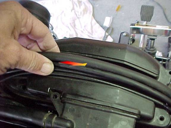
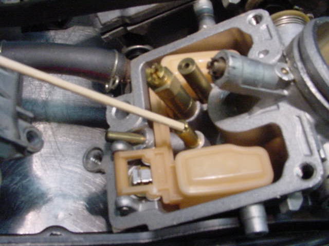
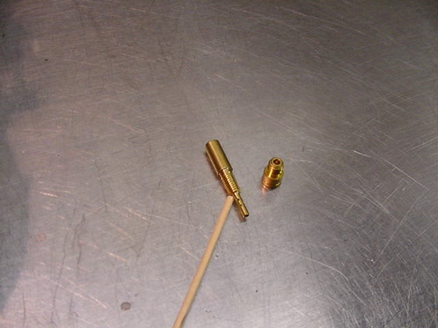
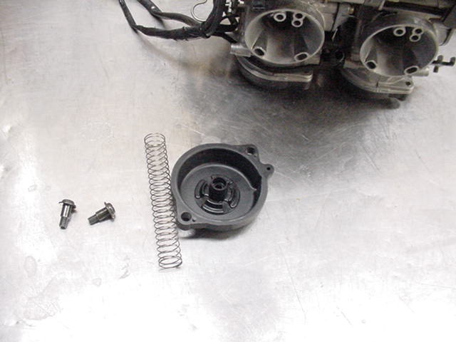
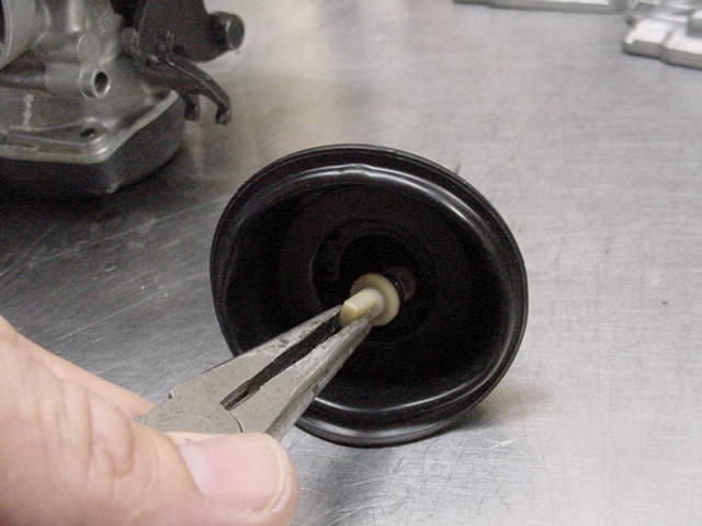
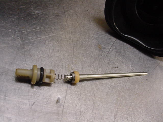
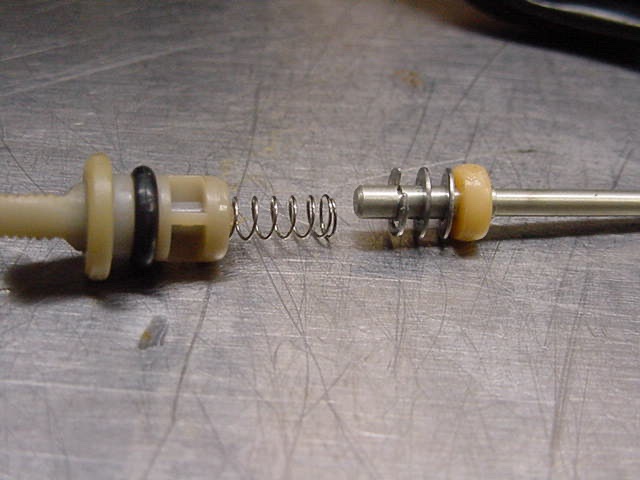
Your Carbtune may need to be cleaned from time to time. The reason is there is small gap in the case that will let dirt and dust in. Looking at the first pic and you can see the gap. How to clean it. First lets understand that it is IMPORTANT that you work on a flat surface and that you keep each rod and spring in its current cylinder. DO NOT MIX THEM UP. Do only 1 at a time. First you will need a small philips head screwdriver. 1. Remove the 2 screws on the bottom of the unit. 2. Carefully remove the cover 3. Carefully remove the foam filler. 4. Slide the cover down and off(says Carbtune on it). 5. Now remove one rod and spring at a time. Clean the rod with a lint free cloth and blow the cylinder out with air pressure. Now put it all back together and the rods should be moving freely again.
-

How to remove the Windshield? 2000 XVZ 1300
Guest posted a topic in Royal Star and Royal Star Tour Deluxe Tech Talk
Hi, I really need to cut my windshield down. Couldn't see a thing in the sun and almost crashed. They should change the angle or something. Gonna get some smoked Lexan and make a cool shorty. Anyway what do I have to do remove to get the windshield off, and in what sequence? It's the full-dresser model with the retro dashboard. PKslice (AKA Geets) -
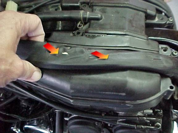
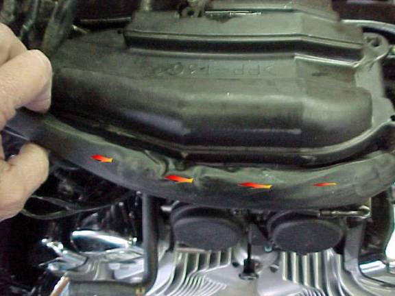
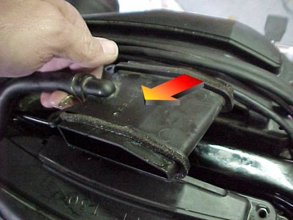
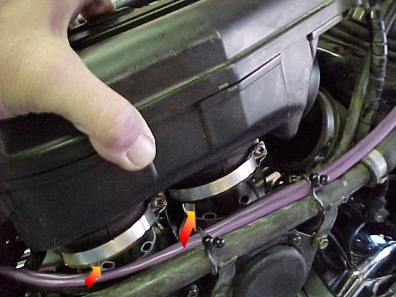
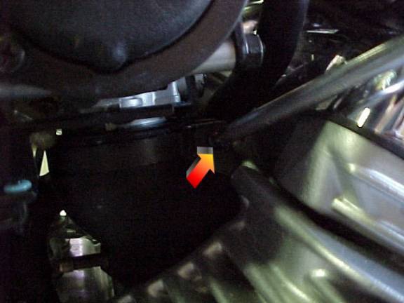
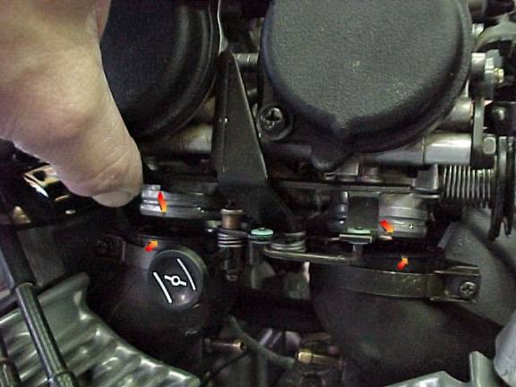
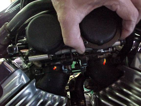
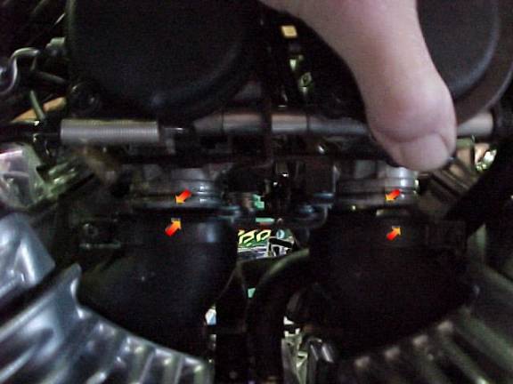
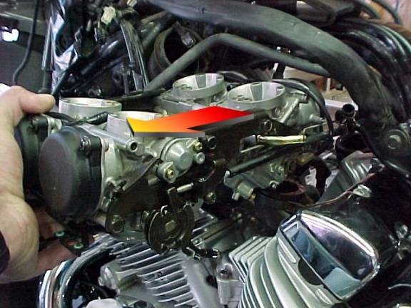
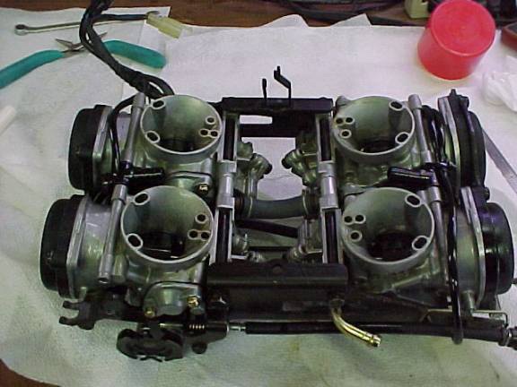
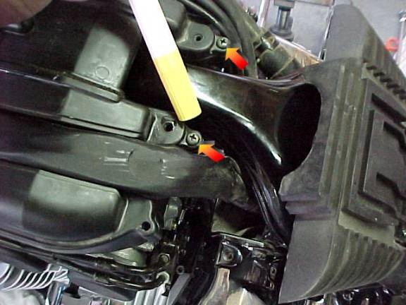
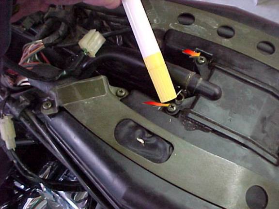
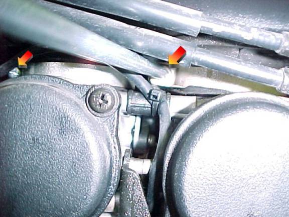
How to remove the carburetors from the '99 to present Royal Star Venture Thanks to Cougar for this excellent article. This was my first time removing the carb cluster from my 2000 RSV. This project took me about 30 to 40 minutes to do including the seat and tank removal. I think it is a pretty easy job to tackle. I tried to take as many pictures as I could. In the write up I used only 2 instead of 5. You will get the idea. 1. Remove the seat and fuel tank. 2. Now you will see the cable and cord clamps. Remove all the screws shown below. 3. No need to remove these screws. 4. Remove this hose from the right surge tank. 5. Now loosen the clamps on the front of the surge tanks (2) as shown below. 6. Now loosen all four clamps on the bottom of the surge tanks that are attached to the top of the carbs in four places, one on each carb. 7. These wires and hose will go towards the middle. 8. Pull the left and right wires and hoses to one side of the surge tanks. Do not worry, they will stretch far enough. 9. Now remove the tank surge union. 10. Now start wiggling and pulling up on each surge tank. 11. Remove one vent hose on each surge tank and then they will be free and out of the way. 12. Remove both left and right overflow hoses from each carb. 13. Next, split apart the two wire connectors on the left side front of the carbs. I think that they are heater and sensor wires. I always have hated the black connectors. 14. Now the fun part. Loosen both nuts on the throttle cable housing. (NOTE: REMEMBER AND MARK THE TOP AND BOTTOM) in the pictures I just remembered that the top nut and lower nut are different. 15. Remove the fuel line from the three holders. 16. Remove these two bolts off the right front carb. NOTE: DO NOT REMOVE THESE TWO SCREWS! (these are to hold the cover on for the carb diaphragm) 17. Loosen all 4 lower clamp screws on the bottom of each carb. 18. Now lift slightly on each side, left and right. 19. Start to pull from the left side about half way and then remove the fuel line that is on the rear middle of the carb cluster. 20. Now the carbs are free from everything. Pull them the rest of the way out from the left side. 21. Find a bucket and turn the carbs over to drain them. 22. Find your favorite work bench and place your carbs on it. 23. Do not forget to fill your intake manifolds with something that will not fall apart to keep the junk out of them. Just a side note for the float bowls. You will need a 4mm hex to remove the 3 screws. The cone shaped brass caps above the hex wrench come off for adjusting the mixing screws. Also, I want say PLEASE make any other comments or suggestions so that Don can add them to this write-up. I hope I explained this for you well.

-
Hello I would like to know how to remove the latch cover inside the trunk of a RSV1999, there is 4 plastic knobs that seems to hold it in place but I don't know how to remove them and don't want to break anything. Is there any special tool needed? Can I use something else? Any trick? I have included a picture from inside the trunk so you can see what I mean. Thanks for your help Hermann
-
I THINK this was written up by Squidley. Installation of the Battery Cable Upgrade As some of you have been patiently waiting for, here is the step by step instructions on how to install the Battery Cable upgrades on the 1st gen. I'm going to try my best to keep it in chronological order for less head aches. I will also mention that you might want to go out and purchase a magnetic tool tray to put all the screws and bolts into so none get lost. If you feel nervous on taking your bike apart this far I would suggest that as your disassembling it you take pictures with a digital camera to aid you in the reinstall. I have done this in the past and it's very helpful. Step 1: Remove the Faux tank cover by opening the fuel door and removing the lower retraining screw. Push forward and then lift up off the bike. http://www.venturerider.org/batterycables/index.1.jpg Step 2: Disconnect the battery cables (both of them) and screw your retaining bolts back into the posts of the battery so they don't get lost. Pull the cables off to the side, as you will need some room to work around. http://www.venturerider.org/batterycables/index.2.jpg Step 3: You will need to remove the battery from it's tray, to do this you will have to un-strap it from the battery box. There is a rubber strap with metal rings that are in the fore and aft area of the box on the top. Pull the one in the front down to disengage it from it's hook point and then lift the entire fuse block off of the battery. You will need to pull the battery sensor wire (white with Red stripe) apart for the removal of the battery and remove the battery from the bike. Step 4: Next you will need to remover the upper fairing electronics on your left side the radio assy. and on the right the CLASS and CB. Pull them out and remove their cradles as you will also have to remove the top covers where the speakers are molded into. You will need to remove both upper pcs and disconnect all electronic leads so you have a clear area to work in. Remember also to pull the Headlight Adjusting Knob on the left side by pulling it strait back towards you. This will need to be off to facilitate removal of the speakers cover. http://www.venturerider.org/batterycables/index.3.jpg http://www.venturerider.org/batterycables/index.4.jpg http://www.venturerider.org/batterycables/index.5.jpg Step 5: There are 2 crescent shaped grill pieces on both sides of the steering head, the right one has the hazard switch in it. Pull the screws and remove both of these, disconnecting the hazard switch from the wire loom. Step 6: Now it's time to pull the battery box out you will need a 10 mm socket and ratchet with a 6" extension. There are 2 bolts in the bottom of the box that will probably be corroded; I would suggest you spray them down with penetrating oil before you attempt to loosen them. Don’t be surprised if you snap 1 or both of them while trying to remove them, if you do, you can drill and re-tap if it concerns you. One of mine is broken and I really don’t worry about it. http://www.venturerider.org/batterycables/index.6.jpg Now there is a 3rd bolt holding the battery box in, to get to it you will need to remove the auxiliary fuse block which is simply pushed onto a retaining bar as it's encased in a rubber holder. http://www.venturerider.org/batterycables/index.7.jpg Pull up on this assembly and move it out of your way now you'll be able to see the 3rd bolt, which is also a 10mm. http://www.venturerider.org/batterycables/index.8.jpg Step 7: Now your ready to pull the battery box out completely, there is a small trick to this. You want to pull it out from the right side at an angle, as there are 2 prongs on the left side that hold the Starter solenoid. It will take a little finagling but you'll just have to wiggle it out. The solenoid is encased in rubber and that is how it's attached to the box, you'll just have to slide it off the posts to the left. http://www.venturerider.org/batterycables/index.9.jpg Now your area should be clear of all the items necessary to get you cables in from the top down to the sides of the bike. Step 8: Now you have to pull off the 2 side panels the removable ones on both sides of the bike by your legs. Then up to the front and the 2 side shields that are besides the radiator, they are held on by 2 screws each. http://www.venturerider.org/batterycables/index.10.jpg When the screws are out pull the panel strait backwards and disengage it from it's slot and then forward . You can remove the horn brackets if you want but you don’t need to as the side shields will come off with them attached. Step 9: Depending on the year of your bike it might or might not have the lower air dam but this has to come off also just for the space availability, and to get at the starter, (If you don’t have this piece skip to step 10). http://www.venturerider.org/batterycables/index.11.jpg There are 4 Allen head bolts that hold it on, 2 on the sides that are visible and 2 underneath the piece, take them out and remove that air dam. Step 10: Remove the chin bar that holds the 2 lower fairing pieces together, this is usually a Phillips head screw or 10mm head bolt, set this aside. Now to remover the 2 lower fairings with the air vents in them, remove the lower bolts from these assemblies (10mm) first and then come up to the top and remove the 2 Phillips screws that are now visible. http://www.venturerider.org/batterycables/index.12.jpg http://www.venturerider.org/batterycables/index.13.jpg http://www.venturerider.org/batterycables/index.14.jpg http://www.venturerider.org/batterycables/index.15.jpg You should now be able to remove both of the lower fairing pieces. Now that your all disassembled it's time to install the new battery cables, this can be tedious and I would suggest that you have another pair of hands to help you as it goes LOTS easier with 2 people. I have done it by myself but you just have to be patient if you try to rush it you'll just get mad. Here's what needs to happen now.... Note; While you have access to the rear cylinder spark plug coils, I would suggest replacing the plug wires while they are accessible http://www.venturerider.org/batterycables/index.16.jpg Installation of the cables Step 1: I would suggest you start with the Negative side first as it is the easiest to install and will boost your confidence a bit before attempting the Positive (note: remember the Positive cables have the red heatshrink the Negative has the black) Take a good look at how the cable is routed before you start, there is a small flexible tab that keeps the cable in place on the frames down tube. http://www.venturerider.org/batterycables/index.17.jpg These will need to be opened up as well as any cable ties that are holding the stock negative cable in place. (Remember to take pics of the routing if you dont feel confident that you'll remember) Now disconnect the Negative cable from the engine block using a 10mm socket or wrench. Step 2: It's totally up to you how you want to run the new cables, you can either pull them down from the top, or pull them up from the bottom. Myself I would pull them up as this is how I have done it in the past, now the fun begins. You will need a good strong cable tie as you are going to connect the old and new cables together.You also need to separate the additional grounding link as it will just be cut off from the cable and a new connector will be crimped onto it. Once this is done you are going to start your Push/Pull method, you will run into some resistance as the new cables are almost twice the diameter of the stock ones, so be paitent. (NOTE: You can apply some WD 40 to the outside of the cable to help the cable slide through). The Negative should pull through fairly easily as there isn't a lot in it's path. Your second set of hands will come in handy here, being up top pulling as you work the cable through it's path from below. Once you get the new portion of cable in the box area http://www.venturerider.org/batterycables/index.18.jpg you'll need to go below and hook up the new cable to the engine block. You can take a pair of vice grip pliers and bend the copper tab over to 90 degrees like the stock one is..this is just for a cleaner look and better fit. Now you can attach the cable back onto the frame tube where it was before and your done with that side. Step 3: Now it's time to do the Positive, this will be a bit more difficult as there is a lot in the area that the cable needs to go through. NOTE: For you who are a bit frazzled right now it might be a good time to get some refreshments ie; a beer or a shot of Beam or just a Root beer and take a break.You are going to do the same procedure as the Negative cable and first remove the Positive cable from the starter which is down inbetween the front exhaust pipes, it's a 10mm nut that holds it on. Remove the rubber nut cover from the stock cable as you can use this again on the new cable. You'll have to split it and re tape it around the new cable or go to your local electrical supply and purchase a bigger one. Then you need to remove the top of the Positive cable from the Starter Solenoid, and separate the fuseable link as it will just be cut off from the cable and a new connector will be crimped onto it. Step 4: This is where it can be aggrivating as you will have to snake the Positive through tighter areas, short pulls win the race here so 2 sets of hands are very helpful in these steps. Some of you might have to loosen the bolts that holds the radio amp (left side) to the frame as I have seen some cables routed through there. I have pictured out where the cable comes up through the battery box area. http://www.venturerider.org/batterycables/index.19.jpg Once you have the cable in the box area you can re attach it to the frame tube and down to the starter, then pull your slack cable up into the box. Remember dont pull it super tight as you still have to install all your other components. Step 5: Replace the short lead from the Solenoid to the battery, Pay attention to how it is twisted and clamped on the solenoid as you will need to have it in a similar shape for the reinstall. I would suggest you do this before you reinstall the battery box as it it will be easier to get to the retaining nut. NOTE; The rubber ends that cover the positive lugs can be reused but you will have to split them to wrap around the thicker cable. I have done this and you can use either electrical tape or a larger heat shrink tube. You can also go to your local electrical supply house and purchase bigger ends to go over the cables. Your almost home free now all that’s left is to start reassembly
-
PROGRESSIVE INSTALL 1983VR BY JACK (justjack) CHALAIS http://www.venturerider.org/progressive/The%20front%20suspension%20of%20my%2083VR%20was%20continually%20bottoming%20out%20due%20to%20some%20very%20old%20fork%20springs_files/progressive06.jpg The front suspension of my 83VR was continually bottoming out due to some very old fork springs. It was time to replace them. Following everyone's advice I decided to install Progressive springs. Here's a blow by blow description of how the job went. Before starting put the bike on it's center stand and place something under the frame front to keep the front tire elevated off the ground. You also need to bleed off any air pressure in the fork tubes using you class computer or Schrader valve. http://www.venturerider.org/progressive/The%20front%20suspension%20of%20my%2083VR%20was%20continually%20bottoming%20out%20due%20to%20some%20very%20old%20fork%20springs_files/progressive05.jpg This is what we needed to remove before getting to the top of the fork tubes http://www.venturerider.org/progressive/The%20front%20suspension%20of%20my%2083VR%20was%20continually%20bottoming%20out%20due%20to%20some%20very%20old%20fork%20springs_files/progressive07.jpg Step 1. Remove the center cover by prying the screw cover off. http://www.venturerider.org/progressive/The%20front%20suspension%20of%20my%2083VR%20was%20continually%20bottoming%20out%20due%20to%20some%20very%20old%20fork%20springs_files/progressive08.jpg The cover is held on by end tabs that can be gently pushed in and upward. http://www.venturerider.org/progressive/The%20front%20suspension%20of%20my%2083VR%20was%20continually%20bottoming%20out%20due%20to%20some%20very%20old%20fork%20springs_files/progressive09.jpg Unscrew the hold down screw and expose the top of the of the steering column. http://www.venturerider.org/progressive/The%20front%20suspension%20of%20my%2083VR%20was%20continually%20bottoming%20out%20due%20to%20some%20very%20old%20fork%20springs_files/progressive10.jpg The next step is to remove the grills on either side of the steering opening. Do the left side first as it is easier and will give you an idea of how the tabs snap in. The right side with the emergency switch is more stubborn, but with persistence it can be messaged out. http://www.venturerider.org/progressive/The%20front%20suspension%20of%20my%2083VR%20was%20continually%20bottoming%20out%20due%20to%20some%20very%20old%20fork%20springs_files/progressive11.jpg You do not need to disconnect the switch, just lay the entire assembly to the side. http://www.venturerider.org/progressive/The%20front%20suspension%20of%20my%2083VR%20was%20continually%20bottoming%20out%20due%20to%20some%20very%20old%20fork%20springs_files/progressive12.jpg Next remove the handle bar nut and center spanner. Hint: a 1 1/8th inch socket will fit the nuts. We borrowed this one from a neighbor. The half inch breaker bar is ours. Beats the heck out of a crescent wrench. http://www.venturerider.org/progressive/The%20front%20suspension%20of%20my%2083VR%20was%20continually%20bottoming%20out%20due%20to%20some%20very%20old%20fork%20springs_files/progressive13.jpg The compression screws also need to be loosened. http://www.venturerider.org/progressive/The%20front%20suspension%20of%20my%2083VR%20was%20continually%20bottoming%20out%20due%20to%20some%20very%20old%20fork%20springs_files/progressive14.jpg Before removing your bars off the spline, mark both the top of the spline and the bar as a reference when reassembling. We used a spring loaded center punch, but a nail will do. If you always wanted to readjust your bars but it was too much trouble...here's your chance when putting it back together. http://www.venturerider.org/progressive/The%20front%20suspension%20of%20my%2083VR%20was%20continually%20bottoming%20out%20due%20to%20some%20very%20old%20fork%20springs_files/progressive18.jpgStick the bars back onto the splines to get them out of the way and still be able to turn the front fork.http://www.venturerider.org/progressive/The%20front%20suspension%20of%20my%2083VR%20was%20continually%20bottoming%20out%20due%20to%20some%20very%20old%20fork%20springs_files/progressive15.jpg This is a picture of our secret weapon. To remove the fork caps you will need a 17mm hex key. The only place I could locate one was Sears. I cut off a piece of the long end and soldered it into an old 17mm 6-point socket, 3/8 drive. Makes life a lot easier, and helps not to strip threads when putting the caps back on. Another suggestion is to locate a 17mm by 6" bolt and a couple of nuts to jamb together on the end and use the head to remove the cap. http://www.venturerider.org/progressive/The%20front%20suspension%20of%20my%2083VR%20was%20continually%20bottoming%20out%20due%20to%20some%20very%20old%20fork%20springs_files/progressive17.jpg Here's 'the weapon' in action. http://www.venturerider.org/progressive/The%20front%20suspension%20of%20my%2083VR%20was%20continually%20bottoming%20out%20due%20to%20some%20very%20old%20fork%20springs_files/progressive19.jpgThis is what we found after unscrewing the right side fork cap. Notice the aluminum slag on the tube housing. Not a good sign. The left side was even worse. Inspect the fork caps for damaged threads, and if you find them call your local Yamaha shop to see if they have any in stock. A new plug runs about $27 bucks.http://www.venturerider.org/progressive/The%20front%20suspension%20of%20my%2083VR%20was%20continually%20bottoming%20out%20due%20to%20some%20very%20old%20fork%20springs_files/progressive21.jpgNext remove the drain screw and drain the fork oil. We used plastic ice cream tubs and they worked great. It's also an excuse to go get more 'cookies and cream'....http://www.venturerider.org/progressive/The%20front%20suspension%20of%20my%2083VR%20was%20continually%20bottoming%20out%20due%20to%20some%20very%20old%20fork%20springs_files/progressive22.jpgThe next hi-tech tool you'll need is this very expensive spacer and spring extractor fashioned from an old coat hanger. Works great to remove those items it was designed to remove.http://www.venturerider.org/progressive/The%20front%20suspension%20of%20my%2083VR%20was%20continually%20bottoming%20out%20due%20to%20some%20very%20old%20fork%20springs_files/IMGP2285.jpgWe went ahead and cut one of the spacers supplied by Progressive in half. Using one half for each fork tube. It might have made the fork a little less stiff, but we felt that we still had the CLASS to adjust the final ride.http://www.venturerider.org/progressive/The%20front%20suspension%20of%20my%2083VR%20was%20continually%20bottoming%20out%20due%20to%20some%20very%20old%20fork%20springs_files/IMGP2280.jpgHere's a pic of the parts you will no longer need. The OEM spacers and the OEM springs. Later: When we tried to reinstall the fork tube plugs we ran into a bit of a problem. The plugs had been removed previously and two of three of the starting threads were in pretty bad shape. This caused a lot of problems getting them back in. To lessen the amount of pressure needed to compress the progressives we cut the PVC spacer in half. We also placed the factory spacer end fittings (washers) into the end of the PVC spacer. It just made sense to eliminate any future wearing of the spacer caused by spring action. (forgot to take a pic and I'm not pulling them out just to take a pic.) Side by side the progressives are much longer than the OEM's, and the coil is a heavier gauge. Once we got the plugs to finally re-thread, reassembling was pretty quick. We found that the best way to get the plugs to start threading was use our secret weapon, along with an 18" 3/8ths extension mounted on a ratchet and use short quick burst strokes to get the plug started. All other attempts didn't work. Hope this helps a bit, and makes the job a little easier.
-
Good day, I would like to know how easy is it to remove those chrome moldings on the front fairing on a RSMV 2005. The fairing need to be repainted and I would like to remove those chrome molding and reinstall it later. Thanks.
-
Submitted by Bill Anton If this is something you may need to do (Sunday or Monday when bike shops are closed) print the procedure and put it in your owners manual. DISASSEMBLY PROCEDURE ===================== NOTE: This info is specific to the 1983-1993 Yamaha Venture motorcycle. Make intelligent (safe) changes for other motorcycles. Included in the procedure are REASSEMBLY torque specifications. The size listed is for the socket or wrench, not the bolt thread size. Initial tools required: - ratchet - 3" extension - sockets: 12mm, 14mm, 19mm - 14mm box-end wrench (if you loosen/remove the final drive) - 27mm flat wrench (rear axel nut) - 6mm Allen wrench (front axel pinch bolt) - pliers (for cotter key) OR get a get a 5/32" $0.75 hitch pin clip (Lowes / Home Depot) and never have to hassle with the archaic cotter key again - tie-down strap(s) - carpet / cardboard (for under forks) !! IMPORTANT: Control the bike's weight balance to make it safe to work around. You may have to ADD some WEIGHT to the REAR of the bike (saddlebags & trunk) BEFORE starting the procedure, so the front of the bike doesn't fall when the front wheel is removed in step 13. You should REMOVE everything from the saddlebags & trunk AFTER the front wheel is removed so the rear of the bike doesn't fall while working on the rear wheel. 1. Put the bike on the centerstand. 2. Connect tie-down straps from the bottom of the centerstand legs, to the engine guards. Pull them as snug as practical. 3. To keep the fork tubes from getting damaged in step 10, place a cardboard or carpet (from a car?) under the front tire area. 4. Loosen the right muffler-to-exhaust clamping bolt - 12mm. REASSEMBLY - Torque 14 ft-lbs. 5. Remove the right muffler mounting bolt - 14mm, and remove the muffler. REASSEMBLY - Torque 18 ft-lbs. 6. Remove the rear brake caliper - 2, 12mm bolts. REASSEMBLY - Torque 32 ft-lbs. TIP: Use axel wrench flat end to spread the brake pads during reassemble. 7. Loosen (not remove) the rear axel pinch bolt - 12mm. REASSEMBLY - Torque 14 ft-lbs. TIP: If the cotter key is aligned vertical, file marks on the pinch bolt end of the axel for easier future alignment. If it isn't aligned vertical, make the marks when you have the axel out. 8. Remove the rear axle nut and washer - 27mm flat wrench. *** DO NOT REMOVE THE REAR AXEL NOW *** REASSEMBLY - Torque 110 ft-lbs. TIP: Replace the cotter key with a 5/32" hitch pin (Lowes / Home Depot). 9. Front wheel remove: 1. Remove both brake calipers (2 bolts each) - 12mm. REASSEMBLY - Torque 32 ft-lb TIP: Get 2 pieces of cardboard 4"x4" and fold them in half and insert them between the pads to hold them apart TIP: Use axel wrench flat end to spread brake pads during reassemble. 2. Loosen the front axel pinch bolt - 6mm Allen wrench. REASSEMBLY - Torque 14 ft-lb 3. Remove the front axel bolt - 19mm. REASSEMBLY - Torque 75 ft-lb 4. Remove the front wheel. TIP: When you pull the wheel out, the speedo cable and drive will fall away -- don't worry unless you are over a dirt surface. REMINDER: On reassembly the speedo housing top-tab goes into the fork notch. 10. Carefully lower the front of the bike until the fork tubes are on the cardboard or carpet. 1. Start slowly pulling down on the fairing near the mirrors 2. As the pull-down becomes easier, slide one hand under the fairing for support 3. Squat a little as the fairing gets lower 4. As the weight increases, bring the other hand down for more support ****** REMOVE WEIGHT from the saddlebags & trunk for better counter balance. 11. Remove the rear axle. Notice the caliper bracket washer, it goes between the bracket and the swingarm. 12. Remove the brake caliper bracket. 13. Remove the 4 final drive attaching nuts - 14mm. then reattach one lower nut 1 1/2 turns so the drive shaft can't pull out of the U-joint and waste a lot of time to put it back together. REASSEMBLY - Torque 30 ft-lb 14. Pull the final drive rearward until it is against the nut. This gives a little more clearance to get the tire past the final drive. CAUTION: The wheel and tire weigh about 42 pounds. Be prepared for step 15. 15. Pull the wheel away from the final drive, and out of the swing arm. 16. Roll the rear wheel out under the fender and do what you removed it for. *-*-*-*-*-*-*-*-*-*-*-*-*-*-*-*-*-*-*-*-*-*-*-*-*-*-*-*-*-*-*-*-*-*-*-*-* Removal of the final drive unit at this point is recommended to lube the driveshaft splines (Molybdenum Disulfide Grease) as long as the wheel is off anyway. See the FINAL DRIVE REMOVAL procedure below. *-*-*-*-*-*-*-*-*-*-*-*-*-*-*-*-*-*-*-*-*-*-*-*-*-*-*-*-*-*-*-*-*-*-*-*-* 17. Reverse the DISASSEMBLY procedures from 14 to 1. - in step 10, do the sub-steps in 3-2-1 order. ---------------------------------------------------------------------- FINAL DRIVE REMOVAL PROCEDURE (optional) ============================= 1. Remove the 4 final drive attaching nuts - 14mm. REASSEMBLY - Torque 30 ft-lbs. 2. Pull the final drive out of the swingarm. NOTE on 86-93 models: The driveshaft oil seal makes the shaft "stick" to the final drive. The driveshaft can be pulled out with a firm force. DO NOT lube 86-93 driveshaft rear splines, final drive fluid lubes them. BE CAREFUL if you pull the shaft out of the final drive, oil can drain from the final drive. FINAL DRIVE REASSEMBLY PROCEDURE ================================ 1. Reinstall the driveshaft: 1. Pull (hard on 86-93 models) the driveshaft out of the final drive. Set the drive aside, being careful to keep it tilted up to prevent fluid loss. 2. Put the transmission in neutral. 3. Use a flashlight, and insert the driveshaft into the swingarm, and use it to align the U-joint so that the yoke is vertical (12 & 6 O'clock), and angled down toward the bottom of the swingarm. 4. Put the transmission in gear (so the U-joint can't turn). 5. Reattach the driveshaft to the final drive. 6. Insert the driveshaft into the swingarm, letting the front end drag on the bottom of the swingarm. 7. Wiggle the wheel mating gear on the final drive to mate the driveshaft with the U-joint - then put the 4 nuts on http://www.venturerider.org/firstgenwheel/Rear%20wheel%20removal%20-%201%20Kneeling%20position%20-%20rear%20view%20(Small).JPG http://www.venturerider.org/firstgenwheel/Rear%20wheel%20removal%20-%202%20Kneeling%20position%20-%20side%20view%20(Small).JPG http://www.venturerider.org/firstgenwheel/Rear%20wheel%20removal%20-%203%20Kneeling%20position%20-%20front%20side%20view%20(Small).JPG http://www.venturerider.org/firstgenwheel/Rear%20wheel%20removal%20-%204%20Kneeling%20front%20view%20(Small).JPG http://www.venturerider.org/firstgenwheel/Rear%20wheel%20removal%20-%205%20Parts%20removed%20in%2010%20minutes%20(Small).JPG http://www.venturerider.org/firstgenwheel/Rear%20wheel%20removal%20-%206%20Centerstand%20tie-down%20strap%20(Small).JPG http://www.venturerider.org/firstgenwheel/Rear%20wheel%20removal%20-%207%20Wheel%20out%201%20(Small).JPG http://www.venturerider.org/firstgenwheel/Rear%20wheel%20removal%20-%208%20Worms-eye%20view%20of%20rear%20wheel%20well%20(Small).JPG http://www.venturerider.org/firstgenwheel/Rear%20wheel%20removal%20-%209%20Rear%20brake%20caliper%20bracket%20position%20pin%20(Small).JPG
-
Splitting the Faring If you ride the second generation Venture long enough, you are eventually going to need to get into the faring. This may be to install passing lamps, repair a loose wiring connection, various reasons. Here are some step by step instructions to make the job easier for you. If you do not have passing lamps already installed, you can obviously skip the first step. If you have passing lamps, you will have to remove them in order to remove the front of the faring. The chrome cover in the center of the passing lamps simply snaps off. http://www.venturerider.org/faring/faring1.jpg Once the chrome comver is removed, there are two bolts that secure your passing lamps. The factory supplies allen bolts for this but mine have been changed out to regular hex heads. If you have allen bolts, a "ball end" allen wrench works best as it allows you to go in at an angle without hitting the bottom of the faring. In the following picture, I have removed the bolts and let the bar rest on my front fender. No need to unwire anything. Note the towel...don't want to scratch that pretty paint do we? NOTE: There are two spacers behind the bracket that you will most likely drop when removing these bolts. Be aware of them. You can usually hold your hand under the bracket as you remove the bolts but I usually end up dropping them anyway. http://www.venturerider.org/faring/faring2.jpg The next step is to remove the top two screws, one on each side, located on the inside of the faring. These two screws hold the top of the faring together and also secure the chrome strip at the bottom of your windshield. http://www.venturerider.org/faring/faring3.jpg Once these two screws are removed, you can carefully lift the chrome strip off. BE CAREFUL HERE. There are tabs molded into the chrome strip that are fairly easily broken. Lift first from each end and gently work it back and forth to separate the tabs from the faring. http://www.venturerider.org/faring/faring4.jpg Once the chrome strip is removed, simply remove the 6 screws that hold the windshield on. http://www.venturerider.org/faring/faring5.jpg After removing those 6 screws, the windshield will just lift out. http://www.venturerider.org/faring/faring6.jpg Now you are ready to remove the remaining 6 screws on the inside of the faring. There are 3 on each side. http://www.venturerider.org/faring/faring7.jpg After removing these 6 screws, the only thing hold the front of the faring on is the screw in the bottom of the headlight ring. I always save this one for last because it enables me to be in front of the bike where I had hold the faring and safely set it aside instead of watching it bounce off the floor. http://www.venturerider.org/faring/faring8.jpg Once you have this last screw removed, gently pull the faring off the headlight and set it aside. That's all there is to it. This is what you'll have now. http://www.venturerider.org/faring/faring9.jpg Now...regardless of why you took your faring apart, take the opportunity to check the connections for your audio system and etc. The big connectors are known to cause problems sometimes. In addition to the ones here, there is another one usually tucked under the tape/radio assembly. Simply pull them apart and use some good di-electric grease to ensure that they stay dry and do not corrode. http://www.venturerider.org/faring/faring10.jpg That's all this is to it folks. Putting it back together is just a matter of reversing these instructions and..of course...turning the screws the OTHER direction. A couple of notes though. As you are putting the screws back in the faring...don't snug them down tight until you have them all started..you might need to wiggle it around a bit to get them all started. VERY IMPORTANT. Do NOT overtighten any of the screws. Especially the ones along the top edge that secure the windshield. Yamaha didn't make that top edge thick enough in my opinion and many people have cracked the plastic around these screws. Just snug them down pretty good but not TOO tight.
-
This was originally submitted to me years ago when I had a forum for the Honda Shadow. No reason why it wouldn't work on the Venture also. Polishing the Lower Forks All right, you've added all those chrome accessories to your bike and you look at your lower forks (sliders) and you want to spiff them up. Whether you just don't like that dull, swirling, satin pattern &/or you have nicks and/or scratches - you want them to gleam like the rest of your bike. You find out that to chrome them is not only expensive but you won't be riding for nearly a month (maybe more) because you will have to remove them and send them out. Can't handle the expense or the down time? You can polish them to a lustrous sheen - almost chrome like. This is manual/hand labor - quite a few hours. Your hands will get real tired. If you want a perfect job/end result, you'll wind up spending two afternoons doing it. Plan on a total of 5 to 8 hours, depending on your endurance and what shape your sliders are in before you begin. Road nicks and scratches will be sanded out and require extra time. (Mine were nicked up - this is what prompted me to do this.) Some people have told me they used a Dremel. I did not. My theory was that the Dremel sanding drum is a cylinder and so are the sliders - minimal contact points - most likely leading to furrows and ridges. Even on a flat surface (like the brake reservoir cover) the Dremel will sand in uneven rows/furrows. An orbital palm sander will finish a flat surface much better. This is not the case when doing the sliders. So, I opted for hand sanding, curling my fingers around the sliders and going at it with a graduation of finer grits. You start off with dry sanding and coarse grit, working up to wet sanding and finer grits to achieve a silky smooth finish. It's that simple in theory - and it works - but you have to put a lot of manual labor into it. I am not trying to talk you out of it. I am a realist and want you to know this is not a quick fix. Yet, it's worth it and comes out looking great! You have a few options to make your work easier. You have to remove the fender because there is no clearance to sand between the fender and the sliders. Once you do that, you are free to follow the procedure listed below. You could remove the sliders (but that's a pretty big job!) so you can work on a bench (faster and easier). I only removed the fender, got my camping stool and went at it. You also could apply a (toxic) stripper (now, now) to remove the clear coat from the sliders but I did not want the mess and any possible damage to the rims or spokes. To remove the fender, here is a hint from my mech. Jack up the bike to raise the front end, remove the wheel and use a scissors jack to push/seperate the forks to a wider position (don't over do it, just enough) to allow the fender to come out easily - w/o scraping/scratching the paint. Don't tweak the forks out of shape and damage them - you only need a little extra clearance supplied by the scissors jack! All that said, here's what I did: Starting off with DRY SANDING: 3M Aluminum Oxide for metal 1) medium grit - # 100 - to remove clear coat & smooth out nicks/scratches 2) fine grit - # 230 - to lessen marks of the 120 & the last of nicks/sratches Proceed with WET SANDING (get a pail of water) 3) medium grit - # 400 - really work it, eliminate nicks/scratches and all previous dry sanding marks - only now see #400 abrasions. 4) medium/fine grit - #600 - you're heading for the finish, smoothing it out 5) fine grit - # 800 - keeps getting easier, you are attaining a finished surface 6) finishing grit - #1200 - now you are getting the silky/final surface Optional step: Rubbing Compound (yeah, I'm a perfectionist) 7) tearing up an old T-shirt, creating a "shoe shine boy's" cloth, liberally apply compound to cloth, wrap it around the slider, and pull back alternately on the ends to work the complete surface of the slider to a "glass" smooth surface. Polish the sliders (your choice, Mother's or Simichrome or whatever shines best) 8) using a clean section of that T-shirt, apply polish (I used Mother's) and work that "shoe shine" rag over the complete surface of the sliders. When you stand back to admire your work, you'll be amazed. You'll forget about all the cursing of me that you did. You'll grin or laugh or say something out loud - it'll look that good - and you'll forget how tired your arms and hands are. The jury is still out for me on whether or not to apply a paste wax to the sliders to protect them. I did not. Other people told me that they did. I feared the wax would discolor my labors over time. I did my sliders in December of 98. Five months later and three or four washings, they still look great and shine. I am a low maintenance type of guy as far as cosmetics go. I ride, I don't spend time washing/polishing. I keep my bike garaged and covered - which helps a great deal. I ride to work whenever I can but it's a short commute (darn). I ride every other weekend because I have my kids every other weekend - so I average about 400 miles on those weekends. I mention all this so you understand why I did not put wax on the forks and why I wash the bike only once a month. Hope all this helped and you are completely happy with your polished forks/sliders! I am sure you will be. I hope the maintenance is little and you get to ride that shining beast a whole bunch! Happy motoring... Submitted by Crazy Charley
-
Starter This article should help the do-it-yourselfer understand the probable cause and cure for the starter. The starter is a high speed DC motor that uses carbon brushes much like the ones used in a rechargeable drill motor and can have the same or similar problems. If your starter drags (runs slow) when you try to start the bike in cold weather or when the bike is at operating temperature, you have one of two possible problems: You will need a battery or you need to fix the starter. If the battery is okay, you are going to have to remove the starter from your bike to find the problem. To remove the starter, I would suggest that yon start by removing the radiator and the thermostat housing. I have found the best way to remove the radiator is to take all the hose clamps and four 10 mm bolts on the side, loosen, then pull the top hoses off; then take the bottom ones off using great care with the small hose in the center of the bottom tank. This tube is the only one that is NOT SOLDERED! It is a press fit and if You pry too much or slip and hit it as I did, you will find yourself on the way to the local radiator shop to have it fixed. To remove the thermostat housing, remove the two 5 mm cap head screws at the bottom of the unit and remove the small metal tube; then the large plastic pipe from the housing or the pump. Now remove the two 10 m bolts holding the rear of the starter to the motor and remove it from the motor. NOTE: It's a tight fit, so spray some WD-40 on the front of the starter where it fits into the motor and carefully pry it out. Now that the hard part is done, you should clean the outside of the starter and look for a scribe mark on the front and rear covers where they meet the center part of the housing. Now, remove the two screws that hold the starter together and tap the rear cover off. Note there is an O-ring seal at this joint, so be careful not to damage it! You can now see the rear bearing and the brushes; check them for wear. Carefully remove the front cover and the armature from the center part of the housing. Note this cover also has an O-ring seal. Inspect the parts for rust and wear, use #600 emery paper to clean the corrosion from the commutator. A dirty or corroded commutator is the most likely culprit for a dragging starter with a bad rear bearing running a distant second. If the bearing is stiff when you turn it, try a thin oil or WD-40 on the back of the bearing until it turns freely. This should work unless the bearing is damaged; and in that case, it will have to be replaced. Yamaha does not have a part number for the rear bearing, so take the number off of the bearing and go to your local bearing outlet, then go down to your dealer and have the bearing changed. Check the armature shaft where it fits in the front cover and the gear at the end of the shaft for wear. If you find noticeable wear, the starter will have to replaced. Next, you should check to see that the coating on the copper wires of the armature is not damaged. If you find exposed copper wire, cover it with a coating of shellac, varnish or clear fingernail polish. The last thing to check is the commutator itself. To do this check the spaces between the copper bars to be sure they are free of foreign material and that they are slightly lower than the copper bars. Most starters will only need cleaning, but if the commutator needs work, Page 7-4 of the service manual covers the necessary steps to be taken. If you have decided to replace the brushes, install them before you reassemble the starter. If you found rust inside the starter and you have used the high pressure water at the car wash, you know what to do, or should I say you know what not to do. Reassemble the starter and remember to line up the scribe marks before tightening the screws, and you could also use some non-adhesive silicon to help the O-rings do their job. Test the starter before you install it by using jumper cables and a battery, then test it again after you have it bolted in place. If it passed the tests, reassemble the rest of the bike. Fred Vogt, #01037
-
Frame Front Suspension Fork springs: At the 1985 V-Daze I attended a seminar given by Yamaha Motor Corp. and during that seminar, I asked this question "why do my front forks bottom when I stop on ruff pavement?". The answer "If you have more then 24,000 miles on the bike you should replace the fork springs" I left the seminar and rushed to the Progressive Suspension both and got the last set of after market replacement springs. I have over 176,000 miles on those springs and have been pleased with their continued performance. You can find a link to Progressive Suspension's web site on the links page of this web site. Fork seals: The fork seals on your Venture are tender and if you get even a small neck in the fork tubes they will start leaking! So before you replace the seals be sure to check the tubes for nicks. If you do find nicks, feel them and if you can feel it so can the seal, with a small fine file VERY CAREFULLY smooth only the high spot of the nick. Zerk fittings This article appeared In September l988 Issue of Venture road on page 15 and In 1991 Yamaha installed grease fittings as standard equipment There has been a lot of talk about installing zero fittings on the mono shock assembly and I have heard that at least one Priority Network dealer is doing just that. I decided to start with a set of arms off the wrecked '83 I have in the garage. Although this bike only had 14,000 miles on it, I could see some wear or pitting on all the metal surfaces and after some thought, I set off for the local auto parts store to purchase a 1/4-24 tap, a 7/32" drill, 2 long zerk fittings (11/16" overall) and 3 short ones (9/16" overall). The bill was $5.35 for the lot and as I drove home I could have kicked myself for waiting so long. Procedure... With the bike on the center stand, remove both mufflers and place a board under the rear tire to take the load off the assembly. Then remove the four bolts and the two bearings at the bottom of the mono shock. (Note: There are dust caps on each side of these bearings and they are not all the same, so make a note on where they came from). After you remove and clean both arms, you are ready to get started. I took my time with the first hole between the bushings marked "A", starting with a 1/16" drill, then a 7/32" drill and keeping the tap straight, I tapped the hole and installed one of the short zerks. The bushings marked "B" were not as simple because the '83 Venture has a metal bushing about .030" thick and I felt that the zerk was too long to go straight into the arm, so I used part of the weld to gain a little thickness but a thin washer would also have done the trick. Remember to drill the holes as close to the center as possible so the drill goes through the groove in the center of the bushings. (Note: 1984-87 Ventures have the thicker fiber bushing in the "B" position, so you only need to drill and tap through the one side of the bushing so that the zerk extends a little into the fiber to hold the bushing in place). The last two bushings marked "C" are drilled and tapped through the raised portion and then counter sink the holes with a clearance drill deep enough so the zerk extends into the fiber bashing. After you thoroughly clean the bearing surfaces, re-install the arms back in the bike and use enough grease to insure an even coating. Wipe off the excess grease. Now each time you change oil, give each of the fittings a little shot of grease for a smooth ride. Fred Vogt, #01037 On later models the procedure is the same and on the "C" bushings you will notice a flat spot where it looks like a grease fitting could go. http://www.venturerider.org/pictures/swing.gif Venture Rear Wheel Service You may ask, "Doesn't my dealer do that?" NOT UNLESS YOU TELL, HIM THAT YOU WANT IT DONE. This service should be completed every tire change or 10,000 miles (16,000k) or at least every two years; but in most cases it isn't done because we don't always have a dealer replace our tires and/or we don't tell him to do the work. So if you just bought the bike or you are not sure it has been done, it would be a good time to think about servicing the rear wheel of your Venture. The procedure is fairly simple to do on bikes without a trailer hitch and only a little harder if your bike has one. Remove the rear bags, right muffler, rear brake caliper and deflate the tire; then remove the rear wheel. If your Venture is a 1983, 84, or 85 you will need to remove the rear drive or differential and remove the drive shaft. Clean the drive shaft and coupling, then grease both ends before putting it back in (note: make sure that the shaft goes back into the u-joint. If you are not sure, remove the spring on the boot covering the u-joint and check it. Next clean the spline or gear on the rear drive and grease it with a good quality grease, personally I use a medium Moly based grease. Now find a couple of 2" x 4" and place the rear wheel spline side up on the boards. When you clean the hub and splines off you will see the spring clip or circlip that holds the hub in place; remove this clip and before you remove the hub mark the possession of the hub so you can replace it in the same holes it came from. Now clean the hub and inspect it for wear then apply grease to the inside of the hub and to the six posts that fit into the wheel. Check the o-ring on the wheel to be sure it is in place before you replace the hub and circlip. Check the bearings inside of the wheel and check the bearing movement; if they are rough or worn replace them. Now for the mono shock pivots place a jack under the rear drive to take the strain off of the mono shock then dissemble. Clean and grease all of the pivot points and reassemble (if you have a 90 - 93 or you have had grease fittings installed, just give them a squirt). Before you install the rear wheel take the axle and put it back through the swing arm into the final drive to check the alignment. If you find that it is in a bind you will have to change the wedge shim between the final drive and the swing arm. Check the oil level in the rear drive or replace the oil if it has been 10,000 miles since it was serviced and check the brake pads for wear. You can now reassemble your bike and have another year or two of trouble free riding. Fred J. Vogt, #01037
-
Written by Fred Vogt, submitted by HDHTR. Thanks. To start remove the engine guard on the left side. 1.Remove the shifter and peg or floorboards. 2.Remove the oil 3.Remove mid-gear cover, (the case cover on the left to the rear) this will drain more oil and free the wiring to be removed. 4. Now remove the left front cover. NOTE: this cover is hard to remove because of the magnetic pull on the stator. Note: the position of the shifter shaft as you remove the cover. 5.Place the cover on a suitable work aria so we don’t scare the case. 6.Remove the retainer for the wiring. Remove the retaining ring [This is where you need the Impact Driver] Reverse the above steps to install Thanks to Fred Vogt. He has a picture for everything!!
-
VR-Exhaust Combiner Chamber Repair A.K.A. Fixing the Rattle in The Baffle by Robert Trim My second 1987 Yamaha Venture Royale Exhaust baffle began the 'rattle samba' a short time back. The devil is in the details and a picture is worth a thousand.... well you get the drift. Here's a way I did the surgery 1- You have to drop the entire exhaust system. a- remove mufflers on both sides first. 2 bolts on the rear of the chamber and 2 bolts half way down the mufflers accessible through the passenger's foot rest supports. b- remove the side panels, both sides. c- remove the lower fairing legs, both sides. The lower air dam and plastic cross brace. d- remove allen bolts holding headers to front cylinders. e- loosen 2 bolts in the clamps holding the combiner chamber to the front pipes. f- There are FOUR attach points holding the exhaust collector box to the bike. The TWO front attach are released by removing two 12mm NUTS located on a bracket near the front of the collector box which hold it to the bottom of the engine case. The TWO rear attach points are released by removing two 12mm BOLTS for the exhaust clamps at the bottom end of the rear headers; these are best removed by using a 10" socket extension angled up at a 45 degree angle on either side of the center stand. g- now the fun part... the chamber is not going to come easy. Use a pry bar on either side and work it lose from the rear headers. You will need to work the front headers lose and free so the chamber can drop down. 2- Cut open the chamber. 3- Remove needed baffle screen to get at the baffle. 4- Remove the baffle. 5- Bend opening shut. 6- Have someone weld it shut. It's stainless steel and needs someone with experience. 7- reinstall in reverse order. Make sure you put the chamber in place WITH the front headers attached. An extra set of hands is vital at this point. Here's some of those thousand word photos.... http://www.venturerider.org/baffle/StrippedSideSm.jpg Side plastic, mufflers and front headers off. http://www.venturerider.org/baffle/LowerSectionSm.jpg http://www.venturerider.org/baffle/BafUpperBolts.jpg It's easier to remove the parts with the bike on the center stand until you get to the rear header clamps. Put it on the side stand, use a mirror and drop light on the floor and look up between the frame tube and slightly forward. About the angle of the arrow you see above. The right side is easier to fine than the left so start with that one first. http://www.venturerider.org/baffle/MirrorSm.jpg http://www.venturerider.org/baffle/ScreenIn.jpg http://www.venturerider.org/baffle/CutoffToolSm.jpg The chamber is on it's back and this is 2 steps into the opening process. I used a cutoff tool to cut it open. WARNING... USE safety glasses and leather gloves when using the cutter. The above photo shows the left baffle liner screen already cut out and you can see the down pipe from the rear header connections. http://www.venturerider.org/baffle/BentUp.jpg Bend it open ONLY as far as you need to gain access to the baffle. I needed it 90 degrees open to get the cutoff tool in. If your baffle is flopping fairly freely (very common), open a little and grab with vice grips, twist and pull hard. http://www.venturerider.org/baffle/SideOpen.jpg Here both screens are cut out. http://www.venturerider.org/baffle/ECUbaffleSm.jpg My baffle had it's welds in place but was stress fractured along the bottom. I simply used the cutter to finish the break. http://www.venturerider.org/baffle/BaffleOut.jpg The rest of the bracket is fine so I leave it. It's spot welded top, bottom and in the front. With the chamber now open for air flow, this now exactly like the crossover pipes put between headers of a dual exhaust system on a car. The VR will now breath much easier. http://www.venturerider.org/baffle/DrillEndCut.jpg Carefully fold the flap back and work it as straight and as close to original placement as possible. Use a drill bit to create a termination hole at the end of each cut. Stainless will crack from any sharp point even after it is welded. http://www.venturerider.org/baffle/ReadyForWeldSm.jpg Ready for welding. A good welder will suggest that after welding the seam, a second layer of stainless be added over the seam. This will pretty much assure that the weld will outlast the bike. http://www.venturerider.org/baffle/CrackedBracket.jpg It is important to check for other cracks. This is the chamber mounting bracket on the top of the chamber. I did not see this until I gave it a good cleaning. This is a common problem. Get it welded as well. http://www.venturerider.org/baffle/BigWeld.jpg Big seam welded to perfection by the students at Salt Lake Community College's welding program. Good people to know. http://www.venturerider.org/baffle/BracketWeld.jpg Bracket crack all fixed. http://www.venturerider.org/baffle/ChamberReady.jpg Ready to go back in place. It's better to approach this from the right side of the bike. Slip the chamber back on the rear header down pipes and thread the bracket bolts on a few turns. Install the front headers into the chamber front inlets. This is a process of seating the pipes into the chamber and, at the same time, making sure the front header seats align flush. Soon as you get it dialed in, put the alan nuts on the front headers to hold them in place. Tighten the chamber bracket nuts. Then tighten the clamps to the front headers, then the header-to-head alan nuts. These are kind of a bear because there is a frame cross brace just 'almost' out of the way. You need a 5/16" longer length alan wrench to get it started. Install the mufflers. Replace the plastic parts and you're good to go. One additional tweak it to drill out the 2 baffles in the mufflers. You'll need a 1/2" drill bit welded to an 18" rod. Punch a few holes in the baffle on each end of the muffler for more air flow. Hope this helps if you need to do baffle surgery.
-
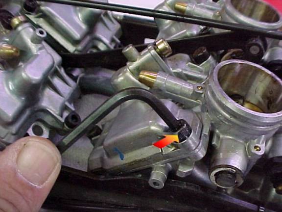
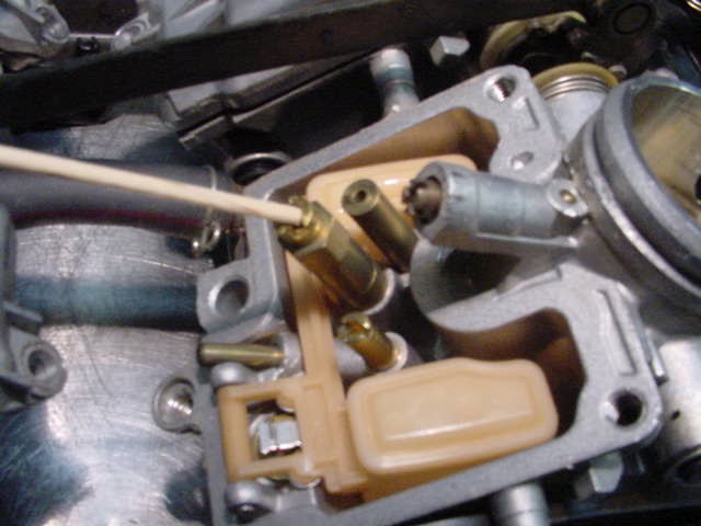
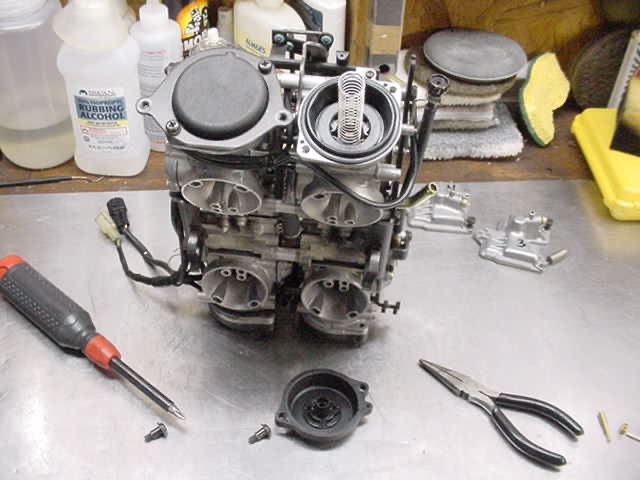
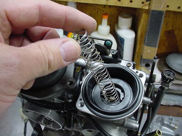
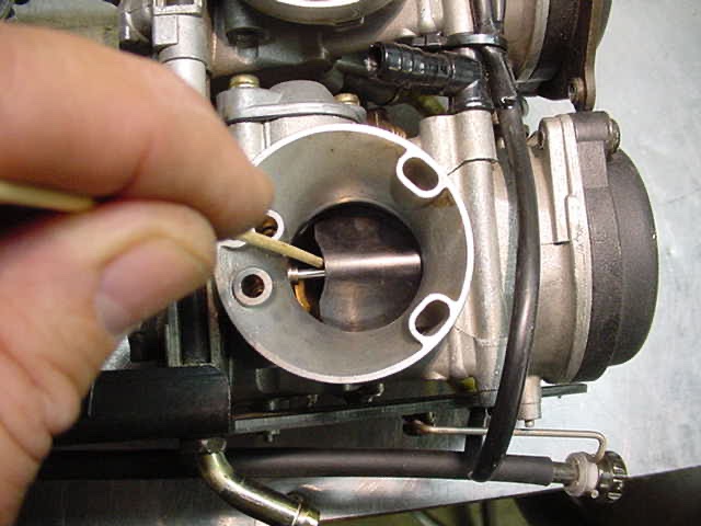
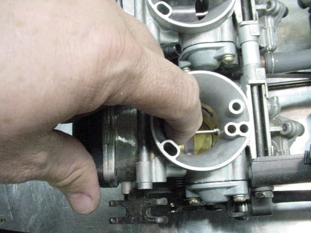
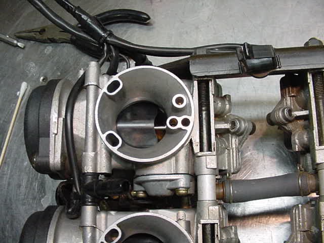
Preface by Don Nelson (Freebird) When Don Murray told me that he was tackling this project, I asked him if he would take some pictures so that we could add them to our tech library. He not only agreed to do so but did a fantastic job of it. Now....is this something you want to do? You'll just have to decide for yourself. The last I heard from Don, he had gone a jet size larger and though he liked the way it ran, a sparkplug inspection seemed to indicate that it was running a little rich. So..he then went a size smaller and didn't feel that it ran as well. So I think he has now gone back to the original main jets and in his case, feels that only the size larger on the pilot jet was needed. That and shimming the needles. Don did a great job so if you find any errors here they are probably my fault in editing. Let me know and I'm make any corrections needed. Re-Jetting the Venture Carbs Thanks to Don Murray for this great write-up After you have removed the carbs and cleaned them set them on a table facing the way you see them in the first picture...it may help you to number them as you see in the picture...you will need to refer back from time to time to make sure you're working on the right carb. The reason I say this is because only two carbs use the same size jets.(1.) Now you'll want to remove the bowls, it may help keep you organize to only remove the bowl of a single carb at a time so you don't install the wrong jet in the wrong carb....don't ask how I know....okay you'll need a #10 allen wrench with a ball end if you don't want to mirer up the bolts...after you get the bowl(s) off this is what you'll see....(2.)(3.) This jet is the main jet! From the factory (stock) it is 122.5 carb #1 122.5 carb #2 117.5 carb #3 120 carb #4 now do you see why I said only remove one bowl at a time....now this only matters if you're changing jets. Here is the main jet after it is removed. It is the one being pointed to with the stick. Okay lets say you want to increase the fuel consumption and maybe increase the HP's (maybe).....without a dyno it's anybody guess if you increased your HP. Okay here's what Joe had said about the correct jet sizes and it worked for me.... carb # 1 up 125 carb # 2 up 125 carb # 3 up 120 carb # 4 up 122.5 along with this jet size increase you should also be using K&N air filters and the "D" cutout in the air filter holders. Now what I found to be a big change was to change the pilot jet....the stock one is 15..replace it with a 17.5 (5.) Here is what the Pilot Jet looks like after you remove it. Again, it is the one pointed to with the stick. The next thing is shimming the needle valves. This is relatively simple and can be done without removing the carbs from the bike if this is the only thing you wish to do. What it will give you is quicker throttle response. Not much commentary here. The pictures tell the story pretty well. Fist thing is to remove the black cover that covers the diaphragms. The spring will just lift out. This is what you have at this point. This is the needle plug holder. Pull it straight out and the diaphragm, slide and needle will lift out. There is an O-Ring here for the vacuum to the diaphragm. Be sure not to lose it. Now...pull straight out on the holder to remove the needle. Here is what the needle assembly will look like. You will want to add some washers to the needle and diaphragm. Now I don't know what Don Murray did but I simply removed one of the washers from the top and and slid it up from the bottom. That shims the needs a bit and is where you get the quicker throttle response. Just disassemble the unit and move one of the washers or buy extra washers from your dealer. Okay...now you just need to put it all back together. After it's back togeher, check the slide. Move it up and let it fall. Use your finger to run this test. If they fall fast rather than just float down as they should, then you probably didn't get the diaphragms back in properly, no sealed. Remove and reinstall them. And that folks, is about it. Reinstall the carbs and go for a ride. If it doesn't run to suit you, just start all over. Jetting is NOT an exact science and unfortunately, it sometimes takes two or three tries to get things the way you want them. Is it worth all the trouble? I don't honestly know....if you try this, maybe you can tell us.
-
Gas Tank Removal Removing the gas tank on the RSV or the Royal Star Tour deluxe is very simple. The question does come up here from time to time though so here are some simple step by step instructions. RSTD may vary slightly. http://www.venturerider.org/gastank/tank1%20(Small).jpg Step 1: Remove the cowling around the gas cap. http://www.venturerider.org/gastank/tank2%20(Small).jpg Step 2: Use a pair of pliars to squeeze the tabs to unplug connector from metal tab. http://www.venturerider.org/gastank/tank3%20(Small).jpg Step 3: Unplug the connector. http://www.venturerider.org/gastank/tank4%20(Small).jpg Step 4: Remove the vent hose. http://www.venturerider.org/gastank/tank5%20(Small).jpg Step 5: Remove single bolt on rear tang of tank. http://www.venturerider.org/gastank/tank6%20(Small).jpg Step 6: Remove push pins that hold bib in place. http://www.venturerider.org/gastank/tank7%20(Small).jpg Step 7: Rubber covers just pull off front mounts. Remove covers and then allen head screws. http://www.venturerider.org/gastank/tank8%20(Small).jpg Step 8: Turn fuel petcock to "OFF" position and them remove gas line. http://www.venturerider.org/gastank/tank9%20(Small).jpg Step 9: Simply lift tank off and set it aside. You are done.
-
Drive shaft maint. On 1st Gen Here is a good article that was written by Mr. Fred Vogt. Fred published a lot of this type articles for the MTA's Motorcycle Roads Magazine. This service should be completed every tire change or 10,000 miles (16,000k) or at least every two years; but in most cases it isn't done because we don't always have a dealer replace our tires and/or we don't tell him to do the work. So if you just bought the bike or you are not sure it has been done, it would be a good time to think about servicing the rear wheel of your Venture. The procedure is fairly simple to do on bikes without a trailer hitch and only a little harder if your bike has one. Remove the rear bags, right muffler, rear brake caliper and deflate the tire; then remove the rear wheel. If your Venture is a 1983, 84, or 85 you will need to remove the rear drive or differential and remove the drive shaft. Clean the drive shaft and coupling, then grease both ends before putting it back in (note: make sure that the shaft goes back into the u-joint. If you are not sure, remove the spring on the boot covering the u-joint and check it. Next clean the spline or gear on the rear drive and grease it with a good quality grease, personally I use a medium Moly based grease. Now find a couple of 2" x 4" and place the rear wheel spline side up on the boards. When you clean the hub and splines off you will see the spring clip or circlip that holds the hub in place; remove this clip and before you remove the hub mark the possession of the hub so you can replace it in the same holes it came from. Now clean the hub and inspect it for wear then apply grease to the inside of the hub and to the six posts that fit into the wheel. Check the o-ring on the wheel to be sure it is in place before you replace the hub and circlip. Check the bearings inside of the wheel and check the bearing movement; if they are rough or worn replace them. Now for the mono shock pivots place a jack under the rear drive to take the strain off of the mono shock then dissemble. Clean and grease all of the pivot points and reassemble (if you have a 90 - 93 or you have had grease fittings installed, just give them a squirt). Before you install the rear wheel take the axle and put it back through the swing arm into the final drive to check the alignment. If you find that it is in a bind you will have to change the wedge shim between the final drive and the swing arm. Check the oil level in the rear drive or replace the oil if it has been 10,000 miles since it was serviced and check the brake pads for wear. You can now reassemble your bike and have another year or two of trouble free riding. Fred J. Vogt, #01037