The
32mm carburetor swap
by
Lynn Nicholls
The
1996 to 2001 Royal Star had a few design shortcomings, leaving its performance
somewhat less than exciting. The
two biggest issues are the carburetors and camshafts, which are too small for
this engine's displacement. Venture
or V-Max camshafts and valve springs are a direct swap into the engine and
present no real difficulties. Swapping
carburetors is another matter. The
intake boots for the stock 28mm carburetors have a different mounting bolt
pattern than anything else, and the heads don't have the needed bosses for the
other mounting bolt pattern, so nothing else will bolt on.
Swapping larger carburetors onto this engine requires some fabrication
one way or another. I toyed with
several ideas for solving this issue, and this is the simplest one I came up
with. This method requires no
drilling, cutting, or welding on the original heads.
None of the original engine parts are modified at all.
Here I will show how to swap the 32mm Venture carburetors onto the
engine.
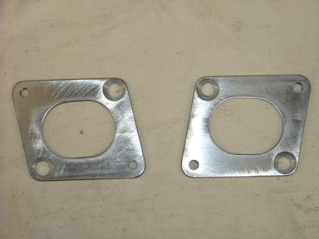
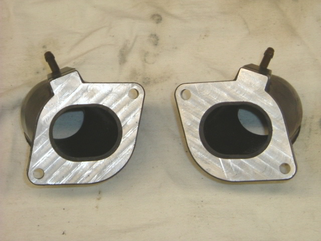
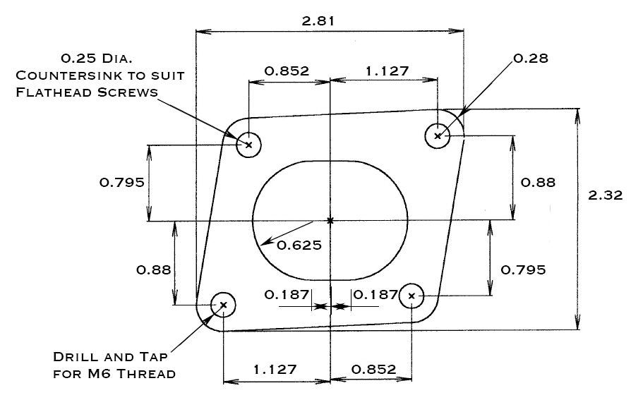
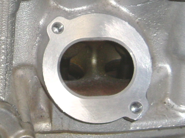
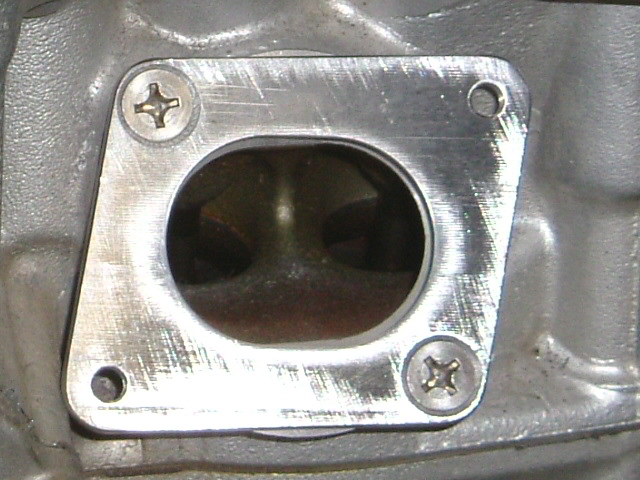
The idea is simple enough - an adapter plate. But just throwing an adapter plate under the intake boots presents a couple other problems. The extra thickness will change the position of the intake boots in a V-engine and then they won't match up with the spacing of the carburetors. The extra thickness will also stand the intake boots and carburetors up higher in the frame and there is no room for that. The solution is to mill the bases of the new intake boots down in the amount of the thickness of the plates. The bases of the intake boots are aluminum and are .355" thick. Milling an 1/8" off of the bases makes them .230" thick, and the bases also extend up about an inch inside the rubber section of the boot, so there is still plenty of rigidity here. Making the adapter plates an 1/8" thick means they need to be made out of steel to have enough strength to do the job. But they don't have to hold very much. They can be painted with a high temperature paint to keep them from rusting, or they can be made from stainless. From a visual standpoint it makes little difference what material is used. When the bike is back together, these adapter plates can't be seen anyway.
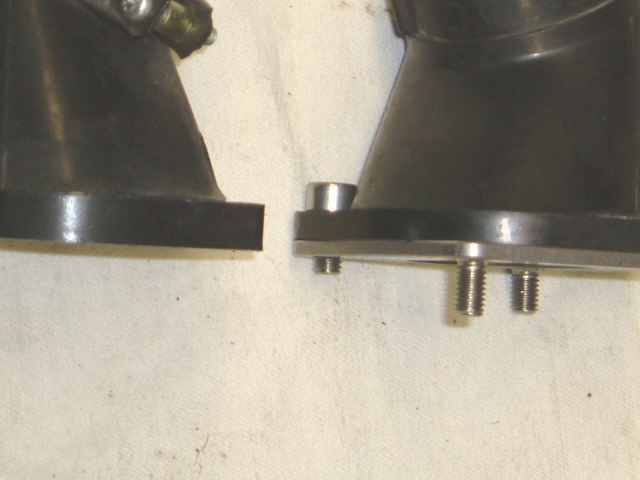
The adapter plates are held to the heads with flathead screws that set flush or slightly below the surface, as the new intake boots will set on top of them. The original intake bolts can be used to hold the new intakes to the plates, or new stainless bolts can be procured. From the drawing given here any machine shop should be able to make the adapter plates. Two of the plates will need to be countersunk from the opposite side as the others, so they are mirror image pairs. Countersink the holes to suit the flathead screws. Milling the bases of the intake boots down also means that the sealing lip is gone from the bottom, but silicone gasket maker can be used to seal things up again. If you want to get really trick you can have the new surfaces of the intake boots and the bottoms of the plates grooved for 1-7/8" diameter 1/16" thick O-rings, like the V-Max intakes are. But silicone works fine. Because the adapters are so thin, it's not a bad idea to use some thread locker on the intake bolts to make sure they don't come loose. When the intakes are bolted down, reach in with your finger and wipe up any silicone that squeezed into the port.
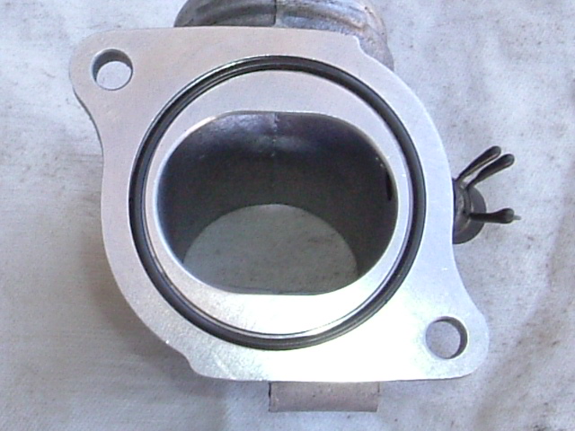
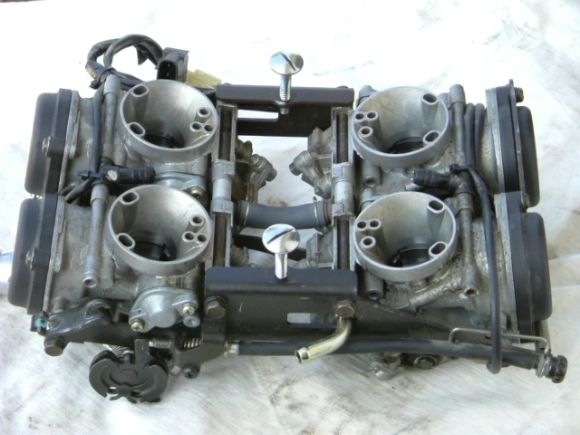
Once the intake boots are bolted down, there are a few other small issues that need to be taken care of to install the carburetors. I changed the direction of the fuel inlet nozzle on the carburetors. It might work as it is, so this may be optional, but I didn't like it. I used a pair of channellocks to twist it 180* where it mounts in the carburetors. It takes some force, but isn't difficult. Then it will be going the opposite direction and the bike's fuel hose will be easier to attach.
The
coolant hose at the top right frame rail needs to be moved outwards a little, or
the carburetors won't slide to the right far enough to match up with the
intakes. Detach the clamps holding
the metal coolant lines to the frame at the front and rear of the rubber hose
and remove the hose. These mounting
points won't be used. The front
metal coolant line will need to be tweaked outward slightly.
I used a large brass punch in the end of the line to pull it out a
little. It doesn't need moved very
much, but do it carefully to avoid kinking the line. The rear coolant line has more flexibility and doesn't need
any tweaking. A slightly longer
piece of hose will be needed to reconnect the coolant lines. A 10" long piece of 3/4" heater hose works fine,
and the rubber sleeve can be slipped back over top of it for a bit of cushion
against the carburetors and the gas tank.
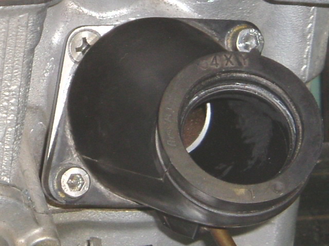
At
this point the carburetors can be slid into the frame and popped into the intake
boots. Actually it may be a good
idea to put the carburetors in place before bending the front metal coolant line
and reattaching the hose. That way
the fit can be made just right the first time and won't need to be readjusted
later. Make the hose fit snugly
against the top edge of the carburetors and just underneath the frame rail.
Route
the vent hoses nicely down to the original brackets and trim them to a
convenient length.
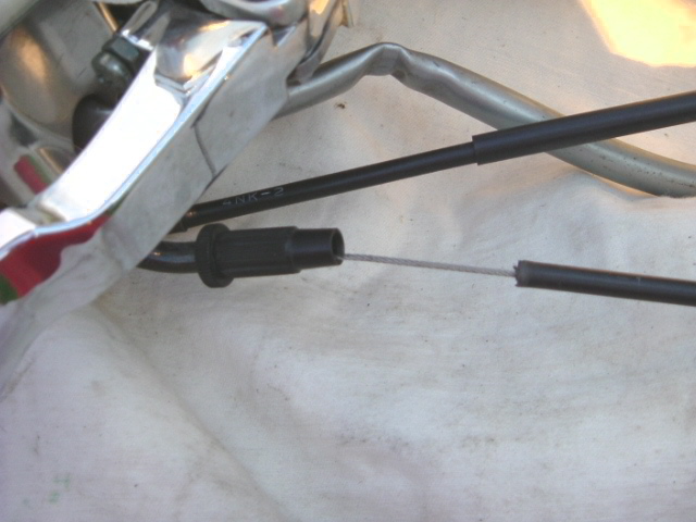
The throttle cables mount on the new carburetors in a different place. They tuck nicely up under the side of the gas tank and are completely out of sight. The problem that comes up here is that the cables are just a bit too short, even after all the cable adjusters have been turned all the way in. My solution for this was to cut about 5/8" off the main cable housing at the throttle grip. The cable will slide out of the adjustable plastic housing there, where it is crimped in place in other locations. I used a Dremel tool with a thin cutoff wheel to cut the housing. It takes some care to avoid nicking the cable itself, and also not to leave a burr on the edge of the housing which would wear the cable out quickly. There is a nylon sleeve inside the housing which helps keep the cables free. Other solutions may also work, but this one seemed easiest and cheapest to me.
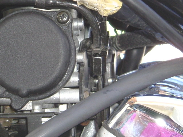
The
bracket on the top left frame rail that holds the main wiring harness and fuel
line will need to be tweaked outwards slightly, and can now be bolted down.
I routed the main throttle cable just behind the bracket, and the return
cable inside the bracket underneath the main wiring harness.
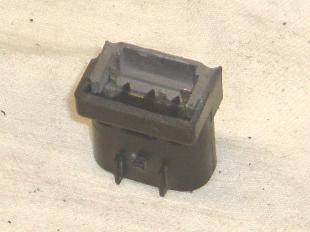
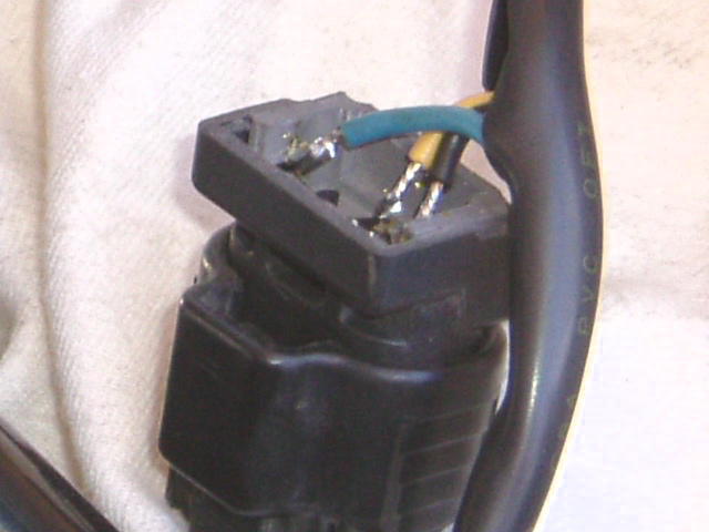
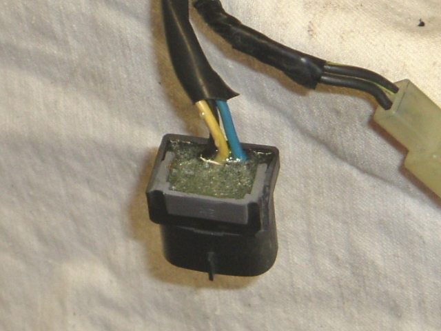
Next is attaching the throttle position sensor wires, as the connectors are different on the 32mm carburetors. Remove the TPS from the 28mm carburetors. Cut the wire connector section off of the 28mm TPS with a hacksaw, and snip the terminals from the main control. Then snip the connector from the TPS wiring on the 32mm carburetors. Make the cut right near the connector and leave the wiring with the TPS. Connect the 28mm TPS connector back onto the bike's wiring harness, and then you can see how to solder the 32mm TPS wires on the connector - black/blue to black, blue to blue, yellow to yellow. If you have a D3K ignition module, you can verify that the TPS is working correctly via the green status LED on the module. When the bike's ignition is first turned on, both red and green LEDs will flash for a second, then go out, indicating the module is on. From idle to about half throttle the green LED will be off, and over about half throttle it will come on. If the green LED stays on all the time, the TPS is either disconnected or may be wired incorrectly. The nuisance of the thing is that the LEDs can't be seen with the module bolted down and the battery in place. The battery will have to be removed and the module unbolted. Then jumper cables can be used to connect the battery to the battery cables on the bike to check the LED. Once you know the TPS is working correctly, mix up a batch of 5 minute epoxy and fill the back of the sawed off connector to protect the soldered terminals. If this method of connecting the TPS wiring fails, any generic three pin wire connector can be used. It's important that the TPS is connected, as it will have a big effect on gas mileage. The TPS does the same job on this bike that the vacuum advance can on the side of the distributor does in an old car. It will vary the spark advance based on engine load. At idle and part throttle the spark needs to advance for the best gas mileage. Under heavier throttle the extra spark advance needs to be taken out to avoid detonation. I had run a couple tanks of gas through the bike before I figured out how I wanted to solve the issue of connecting the wiring. When I got it connected my gas mileage instantly went up by 4 - 5 mpg.
I
didn't wire up the heaters on the 32mm carburetors. My bike didn't originally have heated carburetors, which
means I didn't have the wiring for them. So
I didn't have too much trouble with just leaving the connector dangling.
They are designed to come on when the ambient air temperature is below
about 53* and will turn off when the ambient air temperature is above about 73*.
If they turn out to be necessary, the ambient air temperature sensor
could be procured from Yamaha and wired up with a relay to turn the heaters on
and off. Later bikes apparently did
have the carburetor heaters, but I don't know if the wire connectors are the
same or not. If not, it shouldn't
be too difficult to clip a connector and solder some wires together to get
matching connectors.
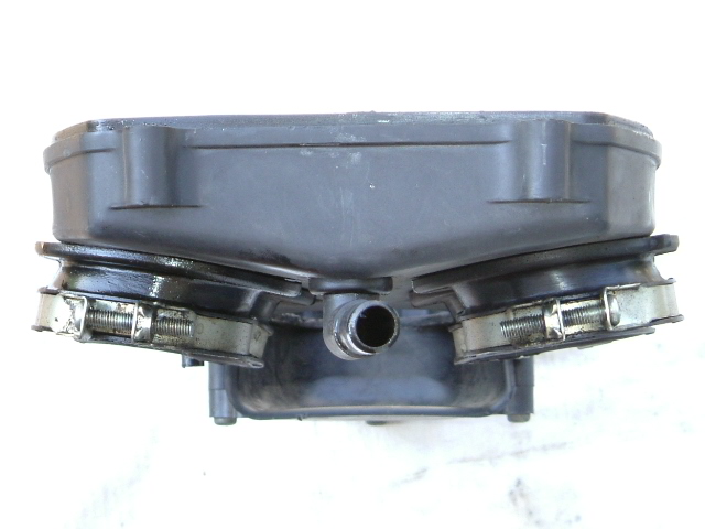
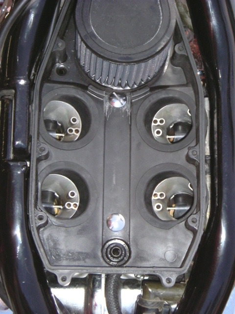
For an airbox I modified and used my previously Bigfooted stock type airbox. The holes in the airbox that hold the rubber boots need to be carved out to 2-5/16" diameter. Carve the holes straight out to the outsides of the box. Don't open them up towards the middle. At their final size they will just touch the outside edges of the airbox. If anything make the holes a little too small so that they hold the boots firmly and they aren't too loose where they could allow air in around them. I trimmed the tops off of the Venture airbox boots with a bandsaw and smoothed them on a bench grinder. Such "velocity stacks" might be a nice feature to have, but they don't fit in this airbox. I rounded off the new upper inside edges of the boots (the short turn radius) with a head porting bit in a die grinder. I ground flat spots on the upper lip with a bench grinder so they will fit tight against the sides of the airbox. When doing this, make sure to orient the boots so that they offset to the outside underneath. You'll need all the width you can get out of them so they will fit onto the carburetors. The lower lip can overhang the outside of the airbox and isn't in the way. It is still just a little bit of a stretch to get the boots onto the carburetors, just enough that I thought they might try to slide themselves off when the clamps were tightened. To prevent that I tapped the holes already in the top of the front and rear main brackets on the carburetors for 1/4" - 20 by 1" long truss head screws, seen in the picture of the fuel inlet. There were cable holders in these holes which aren't needed here. Drill 5/16" holes in the bottom of the airbox for the screws. The rear hole is 1-15/16" from the inside of the back end, and the front hole is 7" from the inside of the back end. The front hole will need to have some of the plastic boss removed at the back of the air filter to clear the screw head. A rubber washer is used under each screw head for sealing against the airbox. A 1/2" plastic spacer is used on each screw in between the carburetor brackets and the bottom of the airbox to give the screws something to tighten up against. The knob is cut off of the front of the airbox lid, and the bracket that used to hold it can also be cut off. That facilitates installing the filter and the top of the airbox once the bottom is screwed down. It is still a bit of a trick though, as the antifreeze overflow hose is still in the way, and the air filter and the top of the airbox have to be slipped into place at the same time. Removing the bolts that hold down the antifreeze fill neck and slipping it sideways also helps a little. A magnetic screwdriver facilitates installing the front two airbox screws. Other air filter arrangements are possible. Four individual pods are a natural, but expensive. A single flat filter setting on top of a custom built airbox also looks interesting, but I haven't tried it yet. I would eventually like to do this one. With any other air filter setup, the jetting will probably need to change from what I have used here.
It's
a snug fit putting the gas tank on now. It
will touch the coolant hose on the right side and the wiring harness and other
hoses on the left side. But if the
hoses and wires are positioned just right it should press down without any
forcing. While the tank is off it's
a good time to ditch the ugly stock fuel valve and get a chrome one for a
Venture.
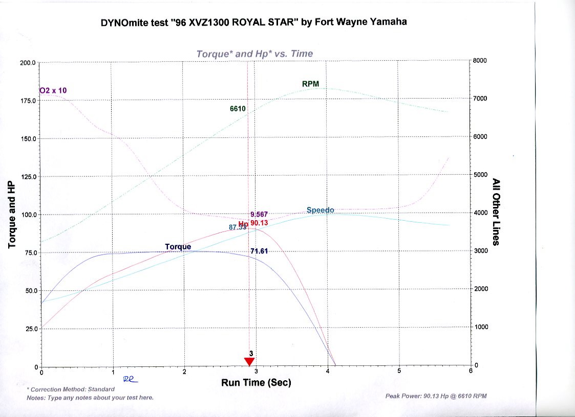
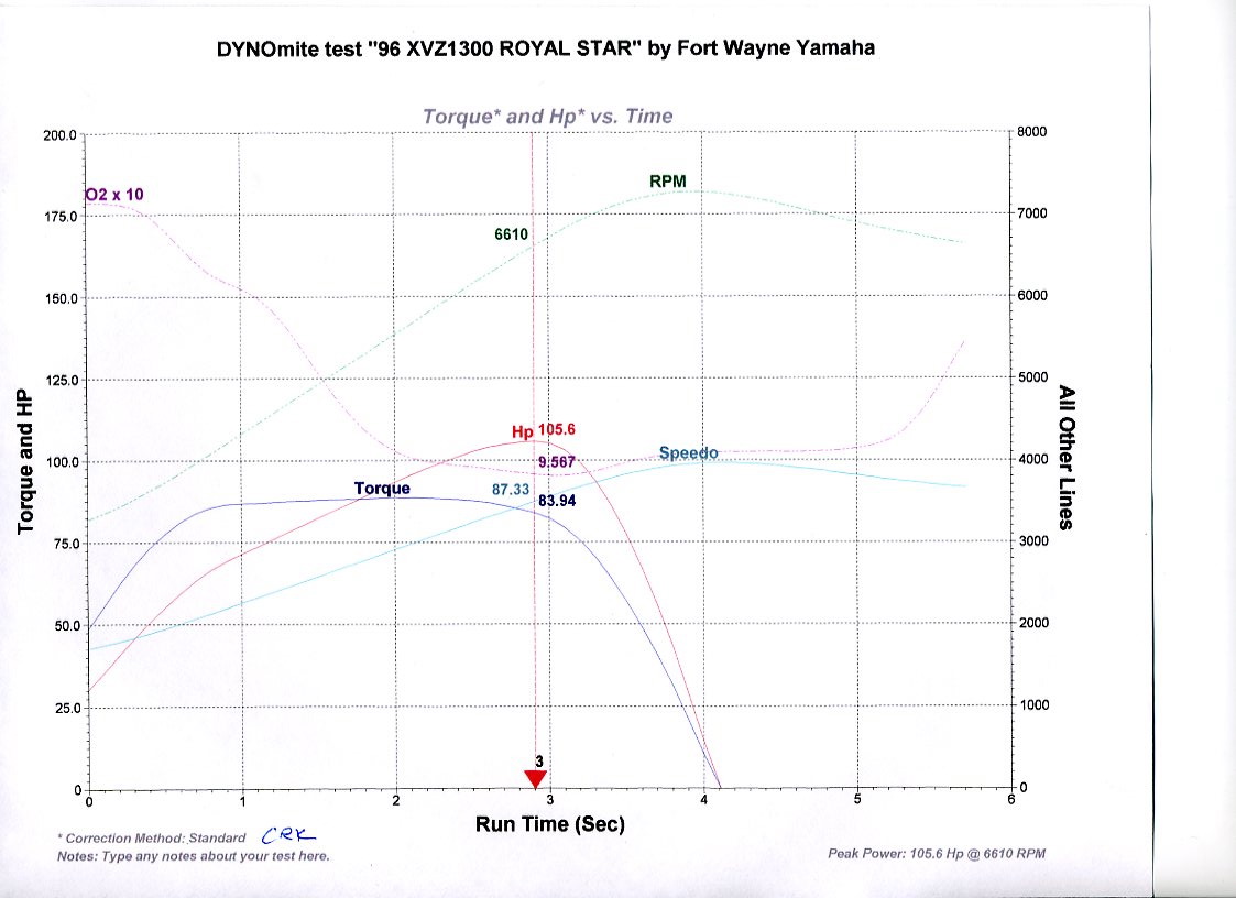
My jetting setup came out to be #17.5 pilot jets, #125 main jets, one shim under the stock needles, and the mixture screws at 3-1/2 turns. I came to this setup going by the performance of the bike, reading plugs, monitoring gas mileage, and ultimately a dyno run. The 32mm carburetors originally had staggered jet sizes, while the 28mm carburetors did not. I started out with all one jet size figuring that I could stagger them later if I thought it was needed. I don't. The dyno run also gave me some horsepower and torque numbers. At the rear wheel my engine is now making 90 hp. @ 6610 rpms. and 76 ft.lbs. @ 5510 rpms. Calculating for 15% losses in the drivetrain, at the crank this comes out to 106 hp. @ 6610 rpms. and 88 ft.lbs. @ 5510 rpms. The torque curve is ruler flat between 4000 rpms. and 6000 rpms. In stock form the bike is rated around maybe 60 hp at the rear wheel. I figure that I increased the hp of my bike by about 50%, and I gave up maybe only about 1 mpg. as an average to get it. I should also mention at this point that I'm running V-Max camshafts and valve springs along with the stock mufflers. With an aftermarket exhaust the jetting may or may not need to change a bit. However, a camshaft swap doesn't normally require a jet change. I'm also using the D3K ignition module on curve 5 rev limited at 8000 rpms., which is the maximum it has available. However, the powerband is essentially done by about 7200 rpms and for maximum acceleration it's time to shift up at that point. With the V-Max rear gear that translates into running first gear up to 45 mph., second gear up to 70 mph., and third gear up to 95 mph.
Swapping
the 32mm carburetors into this bike made a world of difference in performance.
By rights, even these are still too small for this engine's displacement
and the V-Max camshafts, as the V-Max itself uses 35mm carburetors and has 100
fewer cubes. But these are all that
will fit inside the frame without radical surgery.
As it happens I installed the V-Max camshafts while still running the
28mm carburetors. The bigger
camshafts made some difference, but not anywhere near what they could have
because the small carburetors were still holding the engine back.
Ditching the stock 28mm carburetors in favor of the 32mm carburetors
probably has more effect on the performance of the bike than any other
modification. I wouldn't hesitate
to install the 32mm carburetors even on the stock camshafts.
This is not the same bike at all that it was before the carburetor and camshaft swaps. The bike is not cantankerous and is just as drivable and dependable as it was stock. Installing bigger carburetors and camshafts is the real way to unleash the V-Max hiding inside the Royal Star. Nothing else comes close.
Parts
list:
-
32mm carburetors from a '99 or newer Venture or an '05 or newer Tour
Deluxe
-
(2) intake boots - Yamaha
part number 4XY-13586-10-00
-
(2) intake boots - Yamaha
part number 4XY-13596-10-00
-
(4) intake boot clamps -
Yamaha part number 4XY-13575-00-00
-
(4) airbox boots - Yamaha
part number 4XY-14453-00-00
-
(4) airbox boot clamps -
Yamaha part number 90460-58204-00
-
(4) fabricated adapter
plates
-
a 10" long piece of 3/4" heater hose
-
(8) M6 by 12mm flat head
screws (stainless)
-
(8) M6 by 12mm socket head
cap screws (stainless)
-
(2) 1/4" - 20 by
1" long truss head screws
-
(2) rubber washers to fit
the above screws
-
(2) 1/2" long plastic
spacers to fit the above screws
Back to VentureRider.Org Forums